
Internal combustion engine

A technology for internal combustion engines and water injectors, applied to internal combustion piston engines, combustion engines, mechanical equipment, etc., can solve problems such as control and water volume difficulties, and achieve the effects of reducing water consumption and periodic fluctuations

Active Publication Date: 2016-05-11
BAYERISCHE MOTOREN WERKE AG
View PDF6 Cites 2 Cited by
  • Summary
  • Abstract
  • Description
  • Claims
  • Application Information

AI Technical Summary

Problems solved by technology

In addition, the amount of water is difficult to control cycle-dependently due to the wall film

Method used

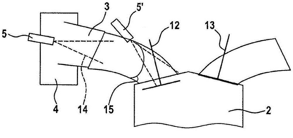

Image

  • Internal combustion engine
  • Internal combustion engine
  • Internal combustion engine

Examples


Embodiment Construction

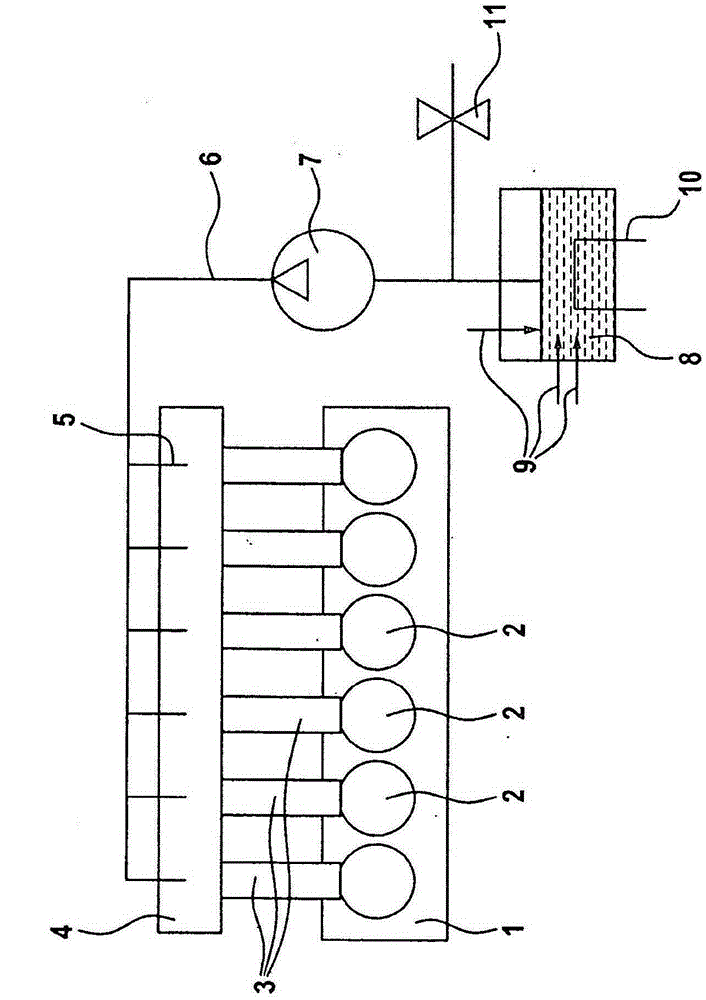
[0017] exist figure 1 A schematic design of an internal combustion engine 1 with a water injection system is shown in .

[0018] Internal combustion engine 1 has a plurality of cylinders 2 which are each connected to an air collector 4 via a surge line 3 . A water injector 5 is provided for each cylinder 2 or each surge line 3 in the air collector 4 . These water injectors 5 are connected via lines 6 to a water pump 7 which in turn is connected to a water tank 8 .

[0019] Various sensors 9 are provided in the water tank 8 , which monitor, for example, the level, temperature, conductivity, etc. of the water. Furthermore, a heater 10 is provided in the water tank. A bypass valve 11 may be provided between the water pump 7 and the water tank 8 .

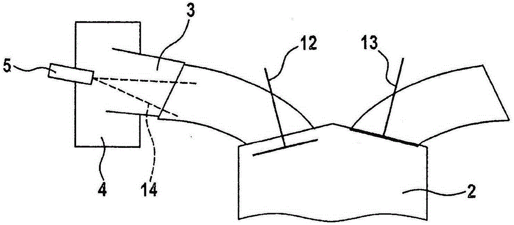
[0020] exist figure 2 A detail of the internal combustion engine 1 is shown in . It can be seen that a cylinder 2 has an intake valve 12 and an exhaust valve 13 .

[0021] The intake valve 12 is connected to the air collector 4...


PUM


Abstract

The present invention relates to an internal combustion engine having at least one cylinder, wherein the cylinder is connected via a pulse tube with an air collector, and with a water injector. In order to avoid the disadvantages of the prior art, as stipulated in the invention, the water injector is disposed in the air collector.

Description

technical field [0001] The invention relates to an internal combustion engine with a water injector and at least one cylinder, wherein the cylinder is connected to an air collector via a surge line. Background technique [0002] Internal combustion engines of this type are known. The water injected into the combustion chamber reduces the engine's propensity to knock and prevents the mixture from becoming rich in order to limit the exhaust gas temperature. Water can enter the tank through different systems, including the following: water is sprayed into the straw. [0003] In this type of straw injection device, water is injected via an injector arranged near the intake valve. [0004] However, this leads to constant wetting of the walls of the inlet channel and the valve disc. Therefore only a small part of the water goes directly into the combustion chamber. Furthermore, the amount of water is difficult to control cycle-dependent due to the wall film. Contents of the ...

Claims


Application Information

Patent Timeline
Patent Type & Authority Applications(China)
IPC IPC(8): F02M25/028
CPCF02M25/0221F02M25/028F02B47/02Y02T10/12
Inventor S·鲁贝特
Owner BAYERISCHE MOTOREN WERKE AG
Learn More