
Combustion-supporting device in the combustion chamber of the drying box of the egg tray machine

A combustion chamber and drying box technology, applied in drying, drying machines, heating devices, etc., can solve the problems of insufficient combustion, pollution, waste of drying energy, etc., and achieve the effect of saving drying energy and reducing pollution

Inactive Publication Date: 2017-10-17
程义浩
View PDF7 Cites 0 Cited by
  • Summary
  • Abstract
  • Description
  • Claims
  • Application Information

AI Technical Summary

Problems solved by technology

If the combustion temperature of the combustion chamber is too low, some fuels such as heavy diesel oil will not be fully burned during the combustion process, which not only wastes drying energy, but also makes the insufficiently burned fuel discharged and pollutes the air environment.

Method used


Image

  • Combustion-supporting device in the combustion chamber of the drying box of the egg tray machine
  • Combustion-supporting device in the combustion chamber of the drying box of the egg tray machine
  • Combustion-supporting device in the combustion chamber of the drying box of the egg tray machine

Examples


Embodiment Construction

[0014] The principles and features of the present invention will be described in detail below in conjunction with the accompanying drawings. It should be noted that the examples given are only used to explain the present invention, and do not constitute a specific limitation to the patent protection scope of the present invention.

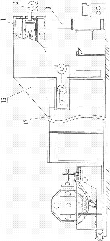
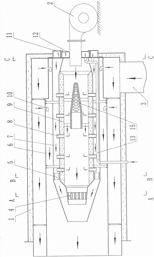
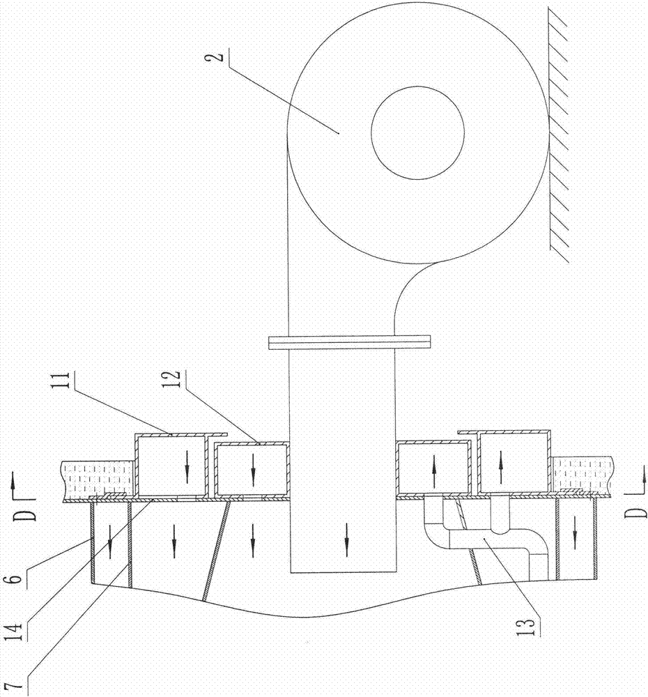
[0015] The combustion-supporting device ( Figure 1-Figure 7 Shown), comprise housing 1 lumen spacer ring sleeve and be connected with cylindrical combustion chamber 6; It is to be connected with outer combustion-supporting chamber 7 in the inner cavity interval of described combustion chamber; Inner combustion chamber 9. In order to increase the temperature at which the pyrotechnics in the internal combustion-supporting chamber are fully combusted, the shell of the internal combustion-supporting chamber 9 adopts a heat storage layer ( figure 2 shown). The outer and inner combustion-supporting chambers 7 and 9 are all connected to each other wi...


PUM


Abstract

The invention discloses a combustion-supporting device of a combustion chamber of an egg tray machine drying box. According to the combustion-supporting device, an inner combustion-supporting chamber and an outer combustion-supporting which are sequentially in looping connection with the combustion chamber in a spaced manner are connected with an air distributing disc on the end face of the combustion chamber; the position, opposite to the air distributing disc, of the outer side face of a shell is in looping connection with an inner air ring and an outer air ring; an end face air inlet hole of the inner air ring and an end face air inlet hole of the outer air ring correspondingly communicate with an end face inner air inlet hole and an end face outer air inlet hole of the air distributing disc; an end face air outlet hole of the inner air ring and an end face air outlet hole of the outer air ring are opposite to an end face inner air outlet hole and an end face outer air outlet hole of the air distributing disc and rotationally communicate with the inner combustion-supporting chamber and the outer combustion-supporting in a fine tuning manner; a hot air outlet of the inner combustion-supporting chamber is connected with an inner combustion-supporting disc; the position close to a hot air outlet of the outer combustion-supporting chamber is connected with an outer combustion-supporting ring in looping connection with the outer diameter of the inner combustion-supporting chamber; and the periphery of the inner combustion-supporting chamber is connected with a guide pipe communicating with the outer combustion-supporting chamber. During work, flames which are not fully combusted are fully combusted through five times of combustion supporting of a conical combustion supporting bypass pipe, the inner combustion-supporting chamber, the outer combustion-supporting chamber, the inner combustion-supporting disc and the outer combustion-supporting d ring, drying energy is effectively saved, and pollution to the air environment is obviously reduced.

Description

technical field [0001] The invention relates to a heating and drying machine; in particular to a combustion-supporting device for a combustion chamber of a drying box of an egg tray machine. Background technique [0002] In the prior art, the combustion device of the drying box of the egg tray machine is that a casing is connected with a casing at an interval ring outside the cylindrical combustion chamber, and a burner is connected with the outer end of the combustion chamber, and the nozzle of the burner is connected with the The inner cavity of the combustion chamber communicates. When working, the fuel such as coal gas, natural gas or diesel from the nozzle of the burner is ignited and injected into the combustion chamber through the ignition device to burn, and the high-temperature heat source generated passes through the hot air outlet of the combustion chamber and enters the drying box through the guide hood. The moist egg tray blanks are dried. Since the fuel needs...

Claims


Application Information

Patent Timeline
Patent Type & Authority Patents(China)
IPC IPC(8): F23L15/00F26B23/02F26B21/00
CPCF23L15/00F26B21/001F26B23/02Y02E20/34
Inventor 程广起
Owner 程义浩
Learn More