Conditioned launch of a single mode light source into a multimode optical fiber

An optical transmitter, single-mode technology, used in optical components, coupling of optical waveguides, light guides, etc.

Inactive Publication Date: 2016-05-11
AVAGO TECH WIRELESS IP SINGAPORE PTE
View PDF1 Cites 3 Cited by
  • Summary
  • Abstract
  • Description
  • Claims
  • Application Information

AI Technical Summary

Problems solved by technology

[0008] Thus, while the use of single-mode laser sources with MMFs would offer advantages in terms of increased bandwidth, increased link length, and reduced transceiver packaging complexity, there are certain hurdles that need to be overcome

Method used


Image

  • Conditioned launch of a single mode light source into a multimode optical fiber
  • Conditioned launch of a single mode light source into a multimode optical fiber
  • Conditioned launch of a single mode light source into a multimode optical fiber

Examples


Embodiment Construction

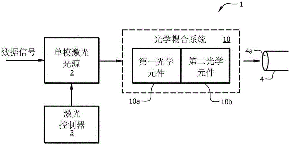
[0025] According to an illustrative or exemplary embodiment described herein, there is provided for reducing back reflection of laser light into an SML light source and for allowing the laser light to avoid defects in the MMF as the light travels through the MMF. Optical coupling systems and methods for coupling light from a single mode laser (SML) source into an MMF by means of controlled emission conditions of the region. The emission conditions are controlled to cause a preselected spatial intensity distribution pattern to be emitted into the MMF, the preselected spatial intensity distribution pattern causing the laser light to avoid the laser light as it passes through the MMF. Defect regions in the MMF described above. The combination of these features allows for greater link bandwidth and link length using MMF without increasing transceiver packaging complexity.

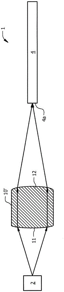
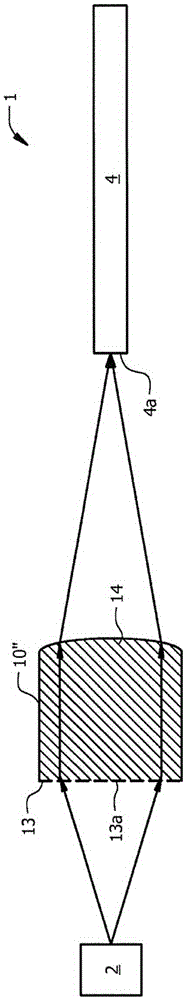
[0026]According to an illustrative embodiment, the optical coupling system includes a first optical element...


PUM


Abstract

The invention provides a conditioned launch of a single mode light source into a multimode optical fiber. An optical coupling system and method are provided for coupling light from a single mode laser (SML) light source into an MMF that reduce back reflection of laser light into the SML light source and provide controlled launch conditions that allow the light to avoid defective areas in the MMF as the light travels in the MMF. The launch conditions are controlled to cause preselected spatial intensity distribution patterns to be launched into the MMF that result in the laser light avoiding defective areas in the MMF as the laser light passes through the MMF. The combination of all of these features allows greater link bandwidth and link length to be achieved with an MMF without increasing transceiver packaging complexity. In addition, because the preselected spatial intensity distributions allow the light to avoid particular areas in the fiber that are likely to contain defects, fiber manufacturers can focus less on reducing defects in those areas and focus more on optimization of performance parameters.

Description

technical field [0001] The present invention relates to fiber optic networks, and more particularly to the use of single-mode light sources with multimode fiber links to increase the bandwidth of the fiber links while also reducing back reflections and allowing for increased link lengths. Background technique [0002] In optical communication networks, optical transceiver modules are used to transmit and receive optical signals over optical fibers. The transceiver module includes a transmitter side and a receiver side. On the transmitter side, a laser light source produces modulated laser light and an optical coupling system receives the modulated laser light and optically couples or images the light onto one end of an optical fiber. The laser light source typically includes one or more laser diodes that generate light of a particular wavelength or range of wavelengths. A laser diode driver circuit on the transmitter side outputs an electrical drive signal that modulates t...

Claims


Application Information

Patent Timeline
Patent Type & Authority Applications(China)
IPC IPC(8): G02B6/42
CPCG02B6/4206G02B6/4286G02B6/4296G02B27/0916G02B27/4233G02B6/4207G02B6/4255
Inventor 陈烨郑安年
Owner AVAGO TECH WIRELESS IP SINGAPORE PTE
Why Eureka
Try Eureka