
Digital light processing (DLP) display system and display control method of laser light source

A technology of laser light source and display system, which is applied in the parts, optics, and television of TV systems, which can solve the problems of not being able to fully utilize the energy of the light source, and achieve the effects of optimizing laser projection display, saving energy, and improving system efficiency

Active Publication Date: 2016-05-11
SICHUAN CHANGHONG ELECTRIC CO LTD
View PDF7 Cites 11 Cited by
  • Summary
  • Abstract
  • Description
  • Claims
  • Application Information

AI Technical Summary

Problems solved by technology

In the traditional technology, when the display system is working, no matter what the displayed content is or the environment in which the system works, the light source and the light source driver always work according to the preset working mode. Such a display method cannot make full use of the energy of the light source.

Method used


Image

  • Digital light processing (DLP) display system and display control method of laser light source
  • Digital light processing (DLP) display system and display control method of laser light source

Examples


Embodiment Construction

[0042] The invention aims to provide a laser light source DLP display system and a display control method to improve the utilization efficiency of the light source.

[0043] The present invention will be described in further detail below with reference to the accompanying drawings and examples. The specific embodiments described here are only used to explain the present invention, not to limit the present invention.

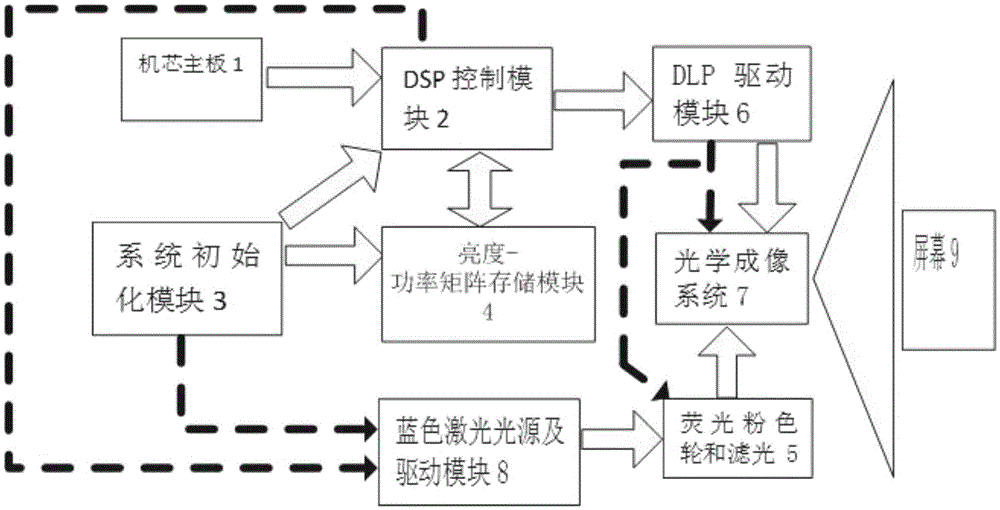
[0044] The laser light source DLP display system in this example includes: core main board 1, DSP control module 2, system initialization module 3, brightness-power matrix module 4, fluorescent pink wheel and filter color wheel system 5, DLP driver module 6, optical An imaging system 7, a blue laser light source and a driving module 8, and a screen 9.

[0045] The DSP control module 2 is connected to the core main board 1, the brightness-power matrix module 4, the initialization module 3, the blue laser light source and the driver module 8 and the DLP driver mod...


PUM


Abstract

The invention relates to a digital light processing (DLP) display system and discloses a DLP display system and display control method of a laser light source, which are used for improving the utilization efficiency of the light source. The display system comprises a machine core mainboard, a digital signal processor (DSP) control module, an initialization module, a brightness-power matrix module, a fluorescent pink wheel and light filtering color wheel system, a DLP driving module, a blue laser light source and driving module, an optical imaging system and a screen, wherein the DSP control module is connected with the machine core mainboard, the brightness-power matrix module, the initialization module, the blue laser light source and driving module and the DLP driving module, the initialization module is connected with the brightness-power matrix module and the blue laser light source and driving module, the blue laser light source and driving module is connected with the fluorescent pink wheel and light filtering color wheel system, and the optical imaging system is connected with the DLP driving module, the fluorescent pink wheel and light filtering color wheel system and the screen. The DLP display system is suitably used for a DLP display screen.

Description

technical field [0001] The invention relates to a DLP display system, in particular to a laser light source DLP display system and a display control method. Background technique [0002] With the development of DLP display technology and projection technology, breakthroughs in semiconductor laser technology make it more and more used as a projection light source in projection systems. There are two ways to use semiconductor lasers as light sources in projection systems: the first is to use red, green, and blue lasers as three primary colors; the second is to use blue lasers as light sources, while the other two The primary colors (that is, red and green) are produced using a blue laser to excite phosphors that emit light. [0003] The second approach is developing most rapidly because it uses relatively cheap blue lasers. The DLP projection system in which the laser excites the phosphor to emit light is composed of a DLP driver board, a signal processing board, a fluoresce...

Claims


Application Information

Patent Timeline
Patent Type & Authority Applications(China)
IPC IPC(8): G03B21/20H04N5/74
CPCG03B21/2053H04N5/7416H04N2005/7433
Inventor 胥立朱晓东毛奎章
Owner SICHUAN CHANGHONG ELECTRIC CO LTD
Learn More