Transition body between tower sections of wind turbine, and tower of wind turbine comprising transition body

A technology of wind power generation equipment and transition body, which is applied in the direction of wind turbines consistent with the wind direction, the assembly of wind turbines, the configuration of installation/supporting wind turbines, etc., which can solve the problems of increasing installation costs and not having force line flux. , to achieve simple installation, reduce the risk of local material damage, and reduce the effect of stress peaks

Active Publication Date: 2016-05-11
THYSSENKRUPP STEEL EURO AG
View PDF10 Cites 0 Cited by
  • Summary
  • Abstract
  • Description
  • Claims
  • Application Information

AI Technical Summary

Problems solved by technology

[0007] The previously described hybrid towers for wind power installations have a so-called disassembled tower structure with a lower tower section of frame construction and an upper tower section formed as a tube, the disadvantage being that the upper and lower tower sections Transitions in between require increased installation costs and do not have optimized flux fluxes (Kraftfluss)

Method used


Image

  • Transition body between tower sections of wind turbine, and tower of wind turbine comprising transition body
  • Transition body between tower sections of wind turbine, and tower of wind turbine comprising transition body
  • Transition body between tower sections of wind turbine, and tower of wind turbine comprising transition body

Examples


Embodiment Construction

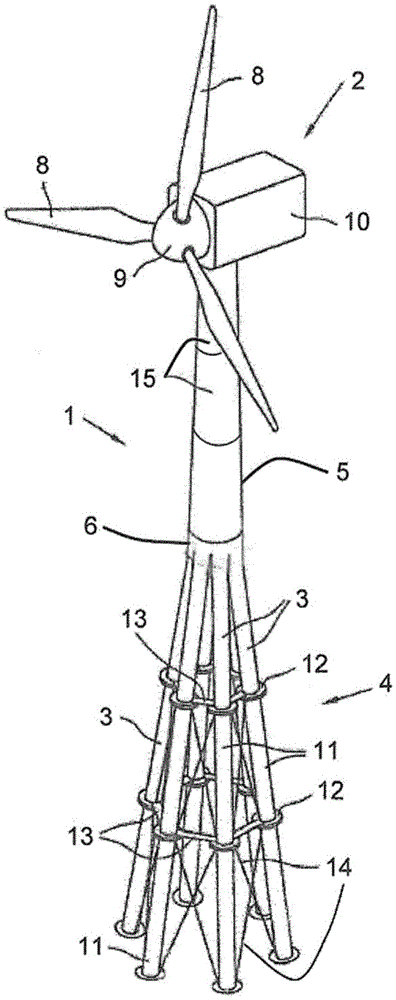
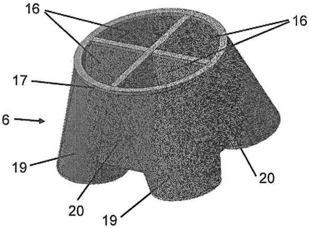
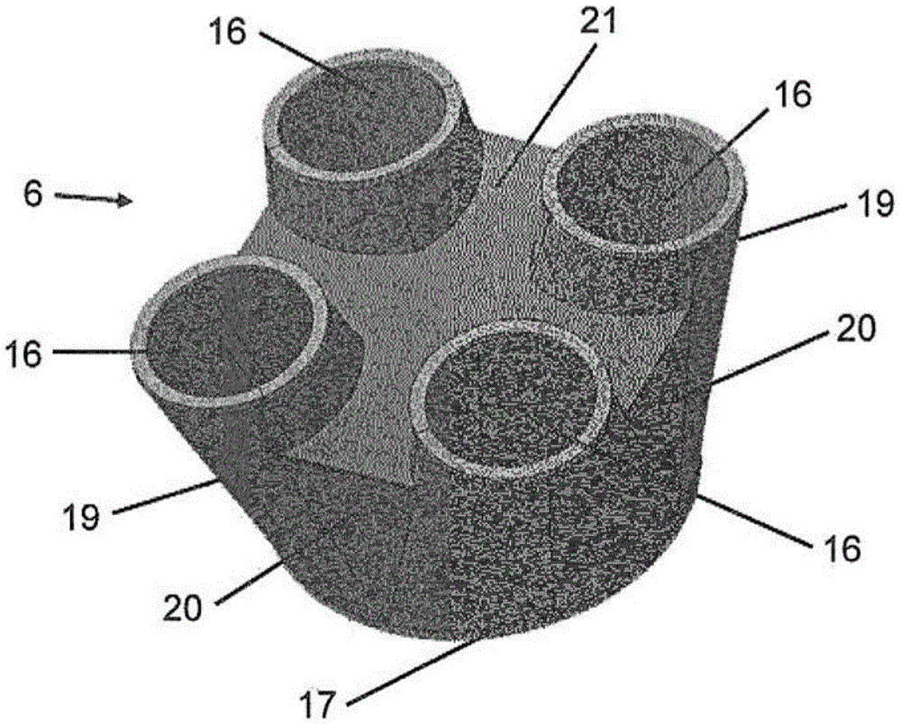
[0036] attached figure 1 The tower 1 of the wind power plant 2 shown in the Fig. The transition body 6 between the lower tower section is formed. On the upper end of the tubular tower of the upper tower section 5 is mounted a wind power plant 2 which is mounted in rotation about an axis extending substantially vertically. The wind power plant 2 includes a rotor 7 rotatable about a horizontal axis with three rotor blades 8 . Furthermore, the rotor blades 8 are mounted rotatably about their longitudinal extent on the hub 9 of the wind power plant 2 in order to be able to operate substantially infinitely towards the wind. In the so-called pod enclosure A generator is set in 10, the shaft of which is rotationally and rigidly connected with the rotor through a transmission mechanism and a coupling.

[0037] The lower tower section 4 has six corner brackets 3 in the illustrated and thus preferred tower 1 , wherein more or less than six corner brackets 3 can also be present. Ho...


PUM


Abstract

What is represented and described is a transition body (6, 6') for arranging between an upper tower section (5) and a lower tower section (4) of a tower (1) for a wind turbine (2), with a substantially annular upper attachment flange for connecting the transition body (6) to an upper tower section (5) and with at least three substantially annular lower attachment flanges in each case for connecting to a corner leg (3) of a lower tower section (4), wherein the transition body (6, 6') has a plurality of segments (16, 16') arranged around a central tower axis, wherein the number of the segments (16, 16') corresponds to the number of the corner legs (3), wherein the upper sections of the segments (16, 16') form, on the outer side of the transition body (6, 6'), an annularly encircling connection shell (17) which bears the upper attachment flange, and wherein the lower sections of the segments (16, 16') in each case form annularly encircling segment shells (19) which bear a lower attachment flange. In order to be able to reduce assembly effort and to improve the flow of forces without this resulting in a disproportionate increase in the outlay on transportation, it is provided in the transition body that the segment shells (19) merge into one another at an acute angle in the upper region at inwardly directed sections.

Description

technical field [0001] The invention relates to a transition body for being arranged between an upper tower section and a lower tower section of a tower of a wind power plant, the transition body having a substantially annular ring connecting the transition body and the upper tower section The upper connection flange has at least three substantially annular lower connection flanges respectively for connection to the corner brackets of the lower tower section, wherein the transition body has a plurality of segments arranged around the central tower axis, wherein the segments The number corresponds to the number of corner brackets, wherein the upper sections of the segments form a ring-circling connecting shell on the outer side of the transition body, supporting the upper connecting flange and wherein the lower sections of the segments each form a ring-circling , The segment shell supporting the lower connection flange. Furthermore, the invention relates to a tower for a wind ...

Claims


Application Information

Patent Timeline
Patent Type & Authority Applications(China)
IPC IPC(8): F03D13/20E04H12/08E04H12/10E02B17/00
CPCF03D13/22E02B17/0004E04H12/085E04H12/10F05B2230/232F05B2240/9121E02B2017/0091Y02E10/728E04H2012/006F03D9/25Y02E10/72Y02P70/50F03D80/70F03D1/0658F03D13/10F03D15/00F03D80/82E04H12/34
Inventor 洛塔尔·帕特博格斯特凡·德鲁斯阿德里安·帕通康斯坦丁诺斯·萨维瓦斯马克·希尔特迈克·柏格奇
Owner THYSSENKRUPP STEEL EURO AG
Why Eureka
Try Eureka