An antenna alignment method, device and system thereof

An alignment device and antenna technology, applied in the field of communication, can solve the problems of lower antenna alignment efficiency, high dependence on skills and experience, and small signal strength range

Active Publication Date: 2019-05-10
HUAWEI TECH CO LTD
View PDF1 Cites 0 Cited by
  • Summary
  • Abstract
  • Description
  • Claims
  • Application Information

AI Technical Summary

Problems solved by technology

[0003] When installing a point-to-point microwave communication system, it is necessary to align the antenna. When the antenna receives a power value, it will be converted into a voltage in the outdoor unit (Out Door Unit, ODU) of the point-to-point digital microwave communication system. At present, the main method of aligning the antenna is The method is to manually adjust the direction of the antenna by the staff, and read the voltage value through the multimeter to judge the alignment of the antenna. Since the antenna is mostly in a high place (for example: iron tower, suburban high ground, etc.), and the antenna beam increases with the frequency band However, the narrowing makes the antenna alignment process more dependent on the skills and experience of the staff, and the range of signal strength that can be detected by the multimeter is small, which reduces the efficiency of antenna alignment

Method used

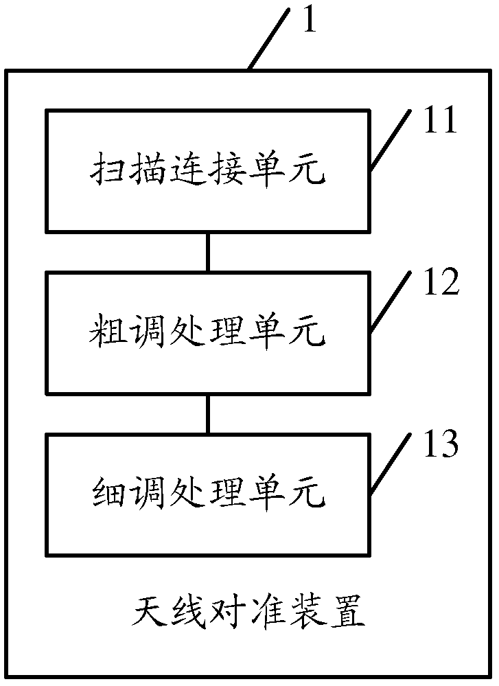
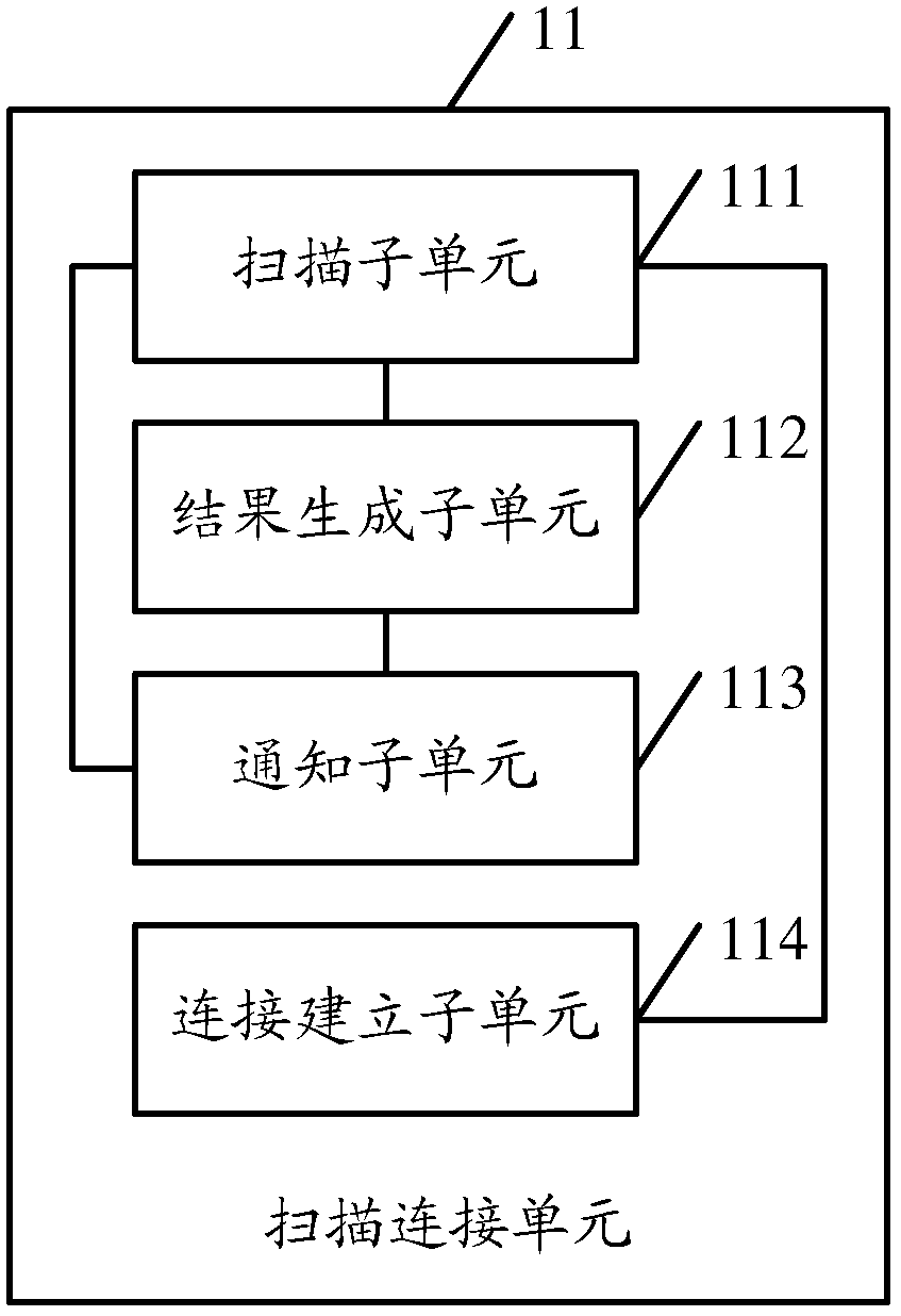
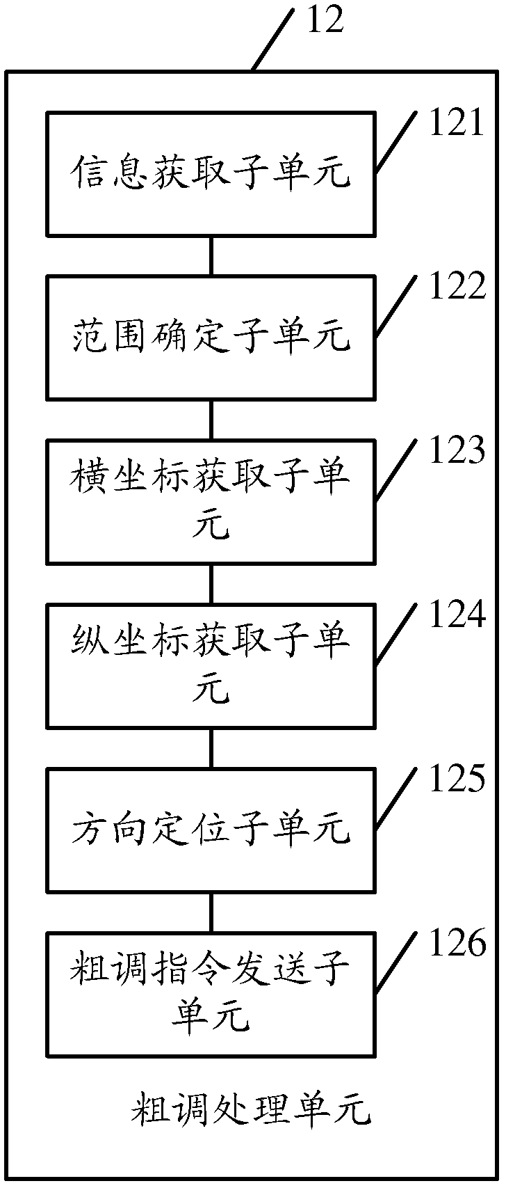

Image

  • An antenna alignment method, device and system thereof
  • An antenna alignment method, device and system thereof
  • An antenna alignment method, device and system thereof

Examples


Embodiment Construction

[0133] The following will clearly and completely describe the technical solutions in the embodiments of the present invention with reference to the accompanying drawings in the embodiments of the present invention. Obviously, the described embodiments are only some, not all, embodiments of the present invention. Based on the embodiments of the present invention, all other embodiments obtained by persons of ordinary skill in the art without making creative efforts belong to the protection scope of the present invention.

[0134] The antenna alignment method in the embodiment of the present invention can be applied to antenna alignment between small base station backhaul equipment, and can also be applied to the alignment between a local antenna with a narrow beam and a target antenna, or one end with a narrow beam and one end with a The alignment between the local antenna of the wide beam and the target antenna, or the alignment between the local antenna of both the wide beam an...


PUM


Abstract

Disclosed are an antenna alignment method, device and system, the method comprising: controlling a local antenna to scan a target antenna according to a sequence of scanning points in a preset distributed dot matrix, acquiring the station information of a target antenna alignment device, and employing the station information of the target antenna alignment device to establish a communication connection with the target antenna alignment device; acquiring local coarse tuning information generated after the scanning of the local antenna, controlling the local antenna to conduct local coarse tuning processing on the target antenna according to the local coarse tuning information, determining the local positioning direction of the local antenna, and sending a coarse tuning instruction to the target antenna alignment device after the local coarse tuning processing; and controlling the local antenna to conduct local fine tuning processing on the target antenna in a local alignment area indicated by the local positioning direction, determining the local alignment position of the local antenna, and sending the fine tuning instruction to the target antenna alignment device after the local fine tuning processing so as to align the local antenna with the target antenna, thus improving the efficiency of antenna alignment.

Description

technical field [0001] The present invention relates to the field of communication technologies, and in particular to an antenna alignment method, device and system. Background technique [0002] The point-to-point microwave communication system refers to the use of microwaves as a carrier to form a link between two points to transmit information. The antenna can concentrate the transmission power of microwaves in a certain area in space, so that microwaves can be transmitted in an approximately linear path in the air. [0003] When installing a point-to-point microwave communication system, it is necessary to align the antenna. When the antenna receives a power value, it will be converted into a voltage in the outdoor unit (Out Door Unit, ODU) of the point-to-point digital microwave communication system. At present, the main method of aligning the antenna is The method is to manually adjust the direction of the antenna by the staff, and read the voltage value through the mu...

Claims


Application Information

Patent Timeline
Patent Type & Authority Patents(China)
IPC IPC(8): H04W88/08
CPCH04B7/0695
Inventor 徐明慧王天祥肖凌文金海焱
Owner HUAWEI TECH CO LTD
Why Eureka
Try Eureka