Bioluminescent fault imaging reestablishment method for directly fusing structure imaging

A technology of bioluminescence and tomography, which is applied in the field of medical image processing, can solve the problems of multi-time, consumption, BLT reconstruction error, etc.

Active Publication Date: 2016-05-18
BEIJING UNIV OF TECH
View PDF3 Cites 11 Cited by
  • Summary
  • Abstract
  • Description
  • Claims
  • Application Information

AI Technical Summary

Problems solved by technology

However, in the fusion of structural imaging, it is often necessary to artificially segment the structural imaging images based on different biological tissue...

Method used


Image

  • Bioluminescent fault imaging reestablishment method for directly fusing structure imaging
  • Bioluminescent fault imaging reestablishment method for directly fusing structure imaging
  • Bioluminescent fault imaging reestablishment method for directly fusing structure imaging

Examples


Embodiment Construction

[0057] The present invention will be described below based on implementation examples and accompanying drawings.

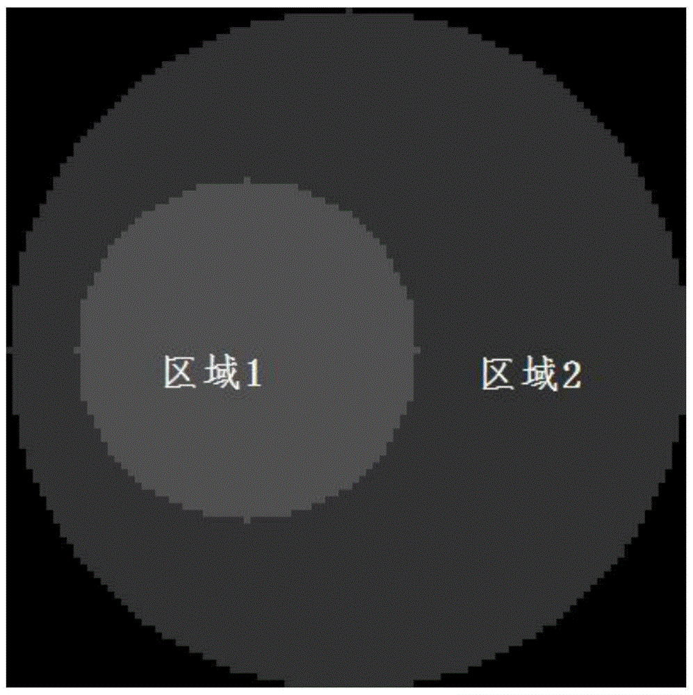
[0058] First, build the phantom with nirfast. In this experiment, a two-region phantom is used. The phantom structure is as follows: figure 1 shown. The number of forward finite element nodes of the phantom is set to 3508. Because the reconstruction results based on single spectrum may not be unique in solving the BLT inverse problem, two bands were used in the experiment. Different light bands have different light absorption coefficients and light scattering coefficients in the phantom. The optical characteristic parameters of the wave bands used in the experiment in the phantom are shown in Table 1.

[0059] Table 1 The phantom optical characteristic parameters of different wave bands

[0060]

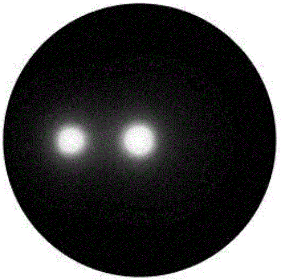
[0061] The initial light source distribution of the phantom obtained by adding light sources is as follows: image 3 shown.

[0062] In general, in order to ens...


PUM


Abstract

The invention provides a bioluminescent fault imaging reestablishment method for directly fusing structure imaging, belongs to the field of medical image processing, aims to solve problems existing in an existing bioluminescent fault imaging reestablishment algorithm and provides a method for conducting BLT reestablishment by fusing other imaging modes; according to the method, reestablishment images obtained through a structure imaging mode serve as apriori information to calculate and obtain a self-adapting regularization matrix, and thus BLT reestablishment is achieved; firstly, the transmission law of light in biological tissues is stimulated based on a diffusion equation, and numerical solution is conducted through a finite element method; BLT reestablishment is conducted to achieve fusing structure imaging, the sparse characteristic of a fluorescent light source is considered, and a method capable of achieving fusing without partitioning structure image tissues is provided; to achieve the solution of the method, an iterative method based on Split-Bregman is proposed.

Description

technical field [0001] The invention belongs to the field of medical image processing, and relates to a bioluminescence tomography reconstruction algorithm directly fused with structural imaging. Background technique [0002] With the continuous exploration of the mysteries of life and the rapid development of modern computer technology, various medical imaging technologies and medical imaging equipment have also entered a period of rapid development. From traditional computed tomography (Computed Tomography, CT), ultrasound imaging (Ultrasound Imaging, USI), magnetic resonance imaging (Magnetic Resonance Imaging, MRI), positron imaging (Positron Emission Tomography, PET), single photon emission tomography (Single-Photon Emission Computed Tomography, SPECT) ) to various imaging modalities such as fluorescence tomography (Fluorescent Molecular Tomography, FMT) and bioluminescence tomography (Bioluminescence Tomography, BLT), these imaging technologies have greatly promoted th...

Claims


Application Information

Patent Timeline
IPC IPC(8): A61B5/00
CPCA61B5/0071
Inventor 冯金超李祎楠贾克斌
Owner BEIJING UNIV OF TECH
Why Eureka
Try Eureka