High-speed accurate laser-beam drilling machine for tablets

A laser drilling machine and laser drilling technology, which are applied in laser welding equipment, welding equipment, metal processing equipment, etc., can solve the problem of the inability to control the size of the diluted micropores on the tablet, the complex mechanical structure of the laser drilling device, and the non-continuous stroke. Production and other issues, to achieve the effect of simple and reliable structure, low noise, reliable and easy to realize

Active Publication Date: 2016-05-18
HANS LASER TECH IND GRP CO LTD
View PDF4 Cites 2 Cited by
  • Summary
  • Abstract
  • Description
  • Claims
  • Application Information

AI Technical Summary

Problems solved by technology

The problems existing in the existing laser drilling device are as follows: 1. The direction and position of the laser drilling are mostly static and fixed. By moving or flipping the tablet, both sides of the tablet can be punched. Therefore, it is necessary to configure a mechanical structure for moving or flipping the tablet so that the entire The mechanical structure of the laser drilling device is complex; 2. The tablet needs to be stationary for a short time when drilling, which cannot be produced continuously, making the drilling efficiency low; 3. The laser beam cannot be adjusted during drilling, and the diluted micropores on the tablet cannot be adjusted. Size; 4. Tablet distributing adopts vibrating plate distributing structure, which has high noise and low distributing efficiency

Method used


Image

  • High-speed accurate laser-beam drilling machine for tablets
  • High-speed accurate laser-beam drilling machine for tablets
  • High-speed accurate laser-beam drilling machine for tablets

Examples


Embodiment Construction

[0032] In order to facilitate the understanding of the present invention, the present invention will be described more fully below with reference to the associated drawings. Preferred embodiments of the invention are shown in the accompanying drawings. However, the present invention can be embodied in many different forms and is not limited to the embodiments described herein. On the contrary, these embodiments are provided to make the understanding of the disclosure of the present invention more thorough and comprehensive.

[0033] Unless otherwise defined, all technical and scientific terms used herein have the same meaning as commonly understood by one of ordinary skill in the technical field of the invention. The terms used herein in the description of the present invention are for the purpose of describing specific embodiments only, and are not intended to limit the present invention.

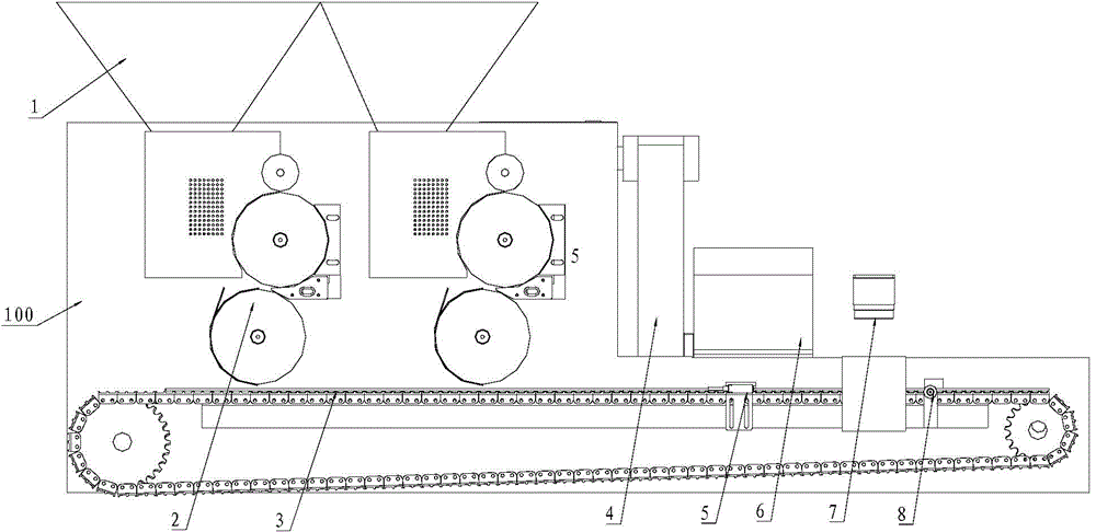
[0034] refer to figure 1 As shown, a high-speed precision tablet laser punching mac...


PUM


Abstract

The invention relates to the technical field of pharmaceutical equipment and discloses a high-speed accurate laser-beam drilling machine for tablets. The high-speed accurate laser-beam drilling machine for tablets comprises a base plate, storage hoppers, one or more sets of distribution steering mechanisms, a conveying chain plate, a laser-beam drilling inductive probe, a laser-beam drilling machine body, a vision camera and a removal device, wherein the conveying chain plate is arranged on the base plate and driven by a sprocket chain; the distribution steering mechanisms are arranged above the conveying chain plate and communicate with the storage hoppers on the side face of the base plate; the laser-beam drilling inductive probe and the removal device are sequentially arranged on the base plate in the conveying direction of the conveying chain plate and located on one side of the conveying chain plate; the laser-beam drilling machine body is arranged on the side face of the base plate and corresponds to the laser-beam drilling inductive probe in position; the vision camera is arranged on the side face of the base plate and located between the laser-beam drilling inductive probe and the removal device. The high-speed accurate laser-beam drilling machine for tablets adopts a mechanical distribution mode, so that the structure is simplified, and cost is reduced; the machine can produce tiny release pores of different pore diameters, thereby improving the efficiency and accuracy.

Description

technical field [0001] The invention relates to the technical field of pharmaceutical equipment, and more specifically relates to a high-speed and precise tablet laser drilling machine for industrial production of controlled-release tablets. Background technique [0002] Controlled-release drug is a kind of slow-release tablet pharmaceutical with a semipermeable membrane on the surface. It usually needs to punch release micropores on the semipermeable membrane. When the preparation is taken, the moisture in the liquid can pass through the semipermeable membrane and enter the inner core of the preparation. , the propellant in the preparation core begins to expand after absorbing water to produce a pump effect-pressure, and the preparation begins to dissolve at the same time, and the increase in pressure forces the dissolved drug to be released slowly through the release micropores punched on the semipermeable membrane and diffuse into it. The human body achieves the purpose o...

Claims


Application Information

Patent Timeline
Patent Type & Authority Applications(China)
IPC IPC(8): B23K26/382B23K26/402B23K26/70B07C5/34B07C5/02B07C5/36
Inventor 陈荣军乌军平欧阳江林许林华高云峰
Owner HANS LASER TECH IND GRP CO LTD
Why Eureka
Try Eureka