Spray head frame positioning device of continuous ink-jet printing production line, and control method thereof

An inkjet printing and positioning device technology, which is applied to printing devices, power transmission devices, printing, etc., can solve the problems of not disclosing the structure of the inkjet positioning device, and not disclosing the specific structure of the inkjet positioning and calibrating device, so as to avoid manual adjustment , high positioning accuracy, and the effect of ensuring printing accuracy

Active Publication Date: 2016-05-18
HANGZHOU HONGHUA DIGITAL TECH +1
View PDF7 Cites 4 Cited by
  • Summary
  • Abstract
  • Description
  • Claims
  • Application Information

AI Technical Summary

Problems solved by technology

[0003] For example, the date of publication is October 15, 2014, and the publication number is CN203876384U in the Chinese patent, which discloses an improved digital printing machine. Nozzle controller and inkjet positioning device, but the specific structure of the inkjet positioning device is not disclosed
Another example is that the publication date is March 13, 2013, and the Chinese patent with the publication number CN202782174U discloses a high-efficiency digital printing machine, which includes a frame, a cloth conveying device, an inkjet positioning calibration device and a printing Inkjet device, but the specific structure of the inkjet positioning calibration device is not disclosed
[0004] To sum up, for the printing of large and wide fabrics, there is currently no nozzle frame positioning device and its control method for the continuous inkjet printing production line with simple structure, reasonable design, and positioning and holding functions, so that the nozzle and the surface of the fabric are in the same position. Keep parallel when printing, so as to realize accurate printing and accurate color registration of CMYK four-color printing unit

Method used


Image

  • Spray head frame positioning device of continuous ink-jet printing production line, and control method thereof
  • Spray head frame positioning device of continuous ink-jet printing production line, and control method thereof
  • Spray head frame positioning device of continuous ink-jet printing production line, and control method thereof

Examples


Embodiment Construction

[0030] The present invention will be further described below in conjunction with the accompanying drawings and embodiments. While the invention will be described in conjunction with the preferred embodiments, it will be understood that it is not intended to limit the invention to the described embodiments. On the contrary, the invention is to cover alternatives, modifications and equivalents, which may be included within the scope of the invention as defined by the appended claims.

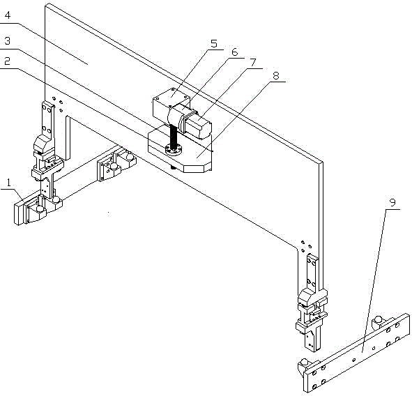
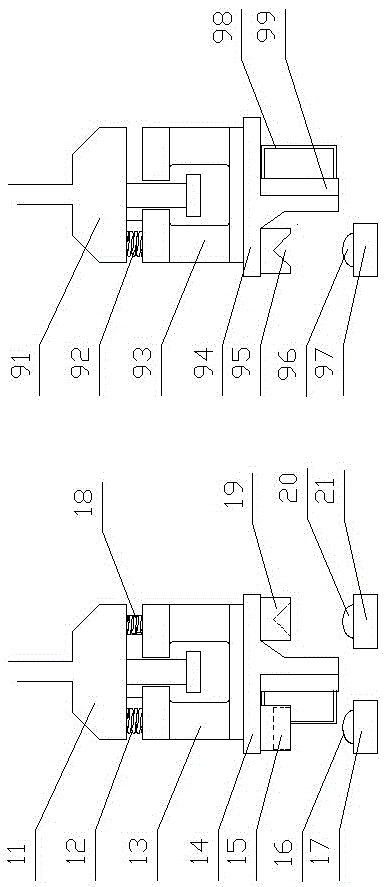
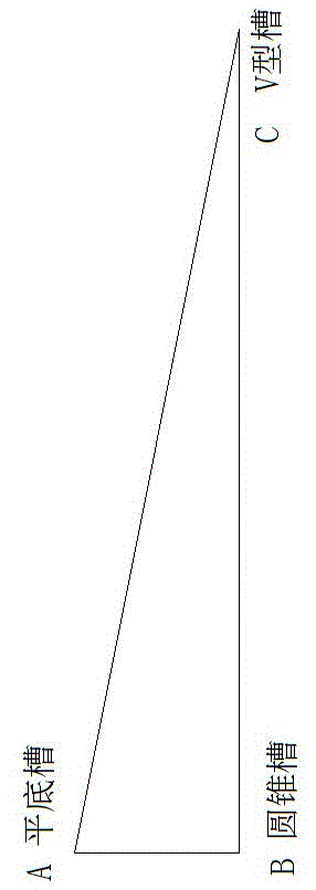
[0031] see Figure 1 to Figure 4 , the nozzle frame positioning device of the continuous inkjet printing production line introduced here is generally used for automatic adjustment and positioning of the overall position of the nozzle frame before printing, but it should be known that the present invention can also be used for automatic adjustment and positioning of other similar positions .

[0032] A nozzle frame positioning device for a continuous inkjet printing production line includes a lef...


PUM


Abstract

The invention relates to a spray head frame positioning device of a continuous ink-jet printing production line, and a control method thereof. The device comprises a left crossbeam lifting plate, a fixed plate, a right crossbeam lifting plate and a transmission mechanism. The device is characterized in that the left crossbeam lifting plate is provided with a fixed block A and a fixed block B, and the fixed block A and the fixed block B are respectively provided with a steel ball A and a steel ball B; the right crossbeam lifting plate is provided with a fixed block C, and the fixed block C is provided with a steel ball C; and the transmission mechanism comprises a nut, a leading screw, a worm and gear, a shaft coupling and a servo motor. The invention provides technical means of integral position adjustment of a large-span spray head frame; the parallelism requirement between a spray head and a fabric surface is effectively met, and the printing precision is ensured; in addition, manual adjustment is avoided, and the production efficiency is improved.

Description

technical field [0001] The present invention relates to a kind of installation tool, more specifically, it relates to a continuous type inkjet printing production line nozzle frame positioning device and its control method. Background technique [0002] The continuous inkjet printing production line is equipped with nozzles in the entire printing width direction, and the nozzles are fixed at the bottom of the nozzle frame as a whole. In order to ensure printing accuracy, each nozzle and the surface of the fabric should be kept parallel during printing. Depends on the position of the nozzle holder, therefore, the overall position adjustment of the nozzle holder before printing becomes particularly important. [0003] For example, the publication date is October 15, 2014, and the publication number is CN203876384U Chinese patent, which discloses an improved digital printing machine. A nozzle controller and an inkjet positioning device, but the specific structure of the inkjet...

Claims


Application Information

Patent Timeline
Patent Type & Authority Applications(China)
IPC IPC(8): B41J2/21B41J3/407B41J25/304B41J29/393
CPCB41J2/2103B41J3/4078B41J25/304B41J29/393
Inventor 陈文华查银洁任锟缪晔李奇志潘骏王瑶何增良徐全伟
Owner HANGZHOU HONGHUA DIGITAL TECH
Why Eureka
Try Eureka