
Embossing machine for both sides

An embossing machine and double-sided technology, which is applied in embossed ornaments, decorative arts, etc., can solve the problems of destroying the external aesthetics of furniture floors, inconsistent textures of upper and lower films, and conveyor belt errors, so as to improve quality and aesthetics and prevent drifting , the effect of convenient operation

Active Publication Date: 2016-05-18
WEMHOENER CHANGZHOU MACHINERY MFG
View PDF6 Cites 0 Cited by
  • Summary
  • Abstract
  • Description
  • Claims
  • Application Information

AI Technical Summary

Problems solved by technology

Traditional furniture floors are usually embossed on one side, but with the continuous improvement of people's living standards, the requirements for furniture floors are getting higher and higher. It has been widely used. At present, the double-sided embossing machines on the market use ordinary electric cylinders. During the operation, the position adjustment value has been set to a fixed value. The conveyor belt will produce a large The error caused the texture of the upper and lower membranes to be inconsistent, which brought great inconvenience to the future installation and also destroyed the external aesthetics of the furniture floor

Method used


Image

  • Embossing machine for both sides
  • Embossing machine for both sides
  • Embossing machine for both sides

Examples


Embodiment 1

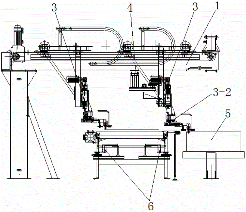
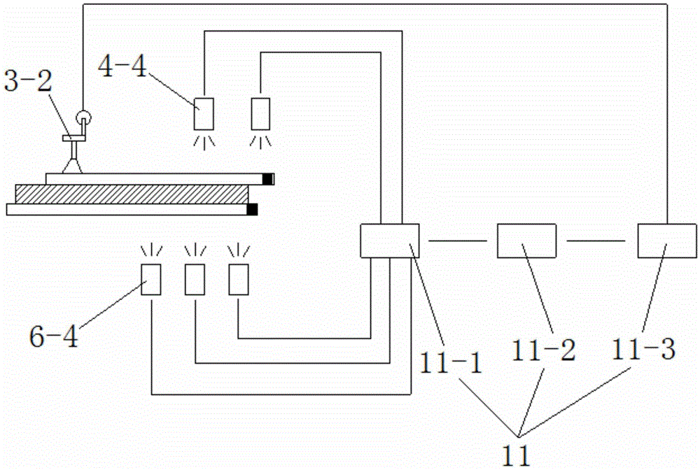
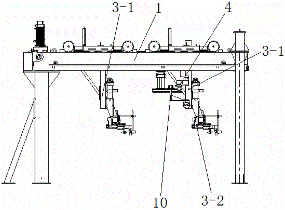
[0028] See Figure 1 to Figure 6 , the double-sided embossing machine of the present embodiment comprises an upper frame 1, a lower frame 2 arranged below the upper frame 1, an upper film transport adjustment mechanism 3 and an upper positioning mechanism 4 installed on the upper frame 1, installed The lower positioning mechanism 6 and the transmission mechanism 7 on the lower frame 2, the work surface 8 installed on the transmission mechanism 7, the electrostatic generator 9 fixed on the work surface 8, installed in the upper positioning mechanism 4 and the lower positioning mechanism 6 The supplementary light mechanism 10, and the control mechanism 11 electrically connected with the upper film transport adjustment mechanism 3, the upper positioning mechanism 4 and the lower positioning mechanism 6.

[0029] Place the substrate with the lower film laid on the workbench 8 . Both the upper film and the lower film are provided with at least one pair of positioning points in the...

Embodiment 2

[0038] This embodiment is basically the same as Embodiment 1, except that it also includes a camera for automatically adjusting the positions of the upper positioning mechanism 4 and the lower positioning mechanism 6, or for automatically adjusting the upper positioning mechanism 4 and the lower positioning mechanism 6. Position automatic position adjustment mechanism.


PUM


Abstract

The invention discloses an embossing machine for both sides. The embossing machine for both sides comprises an upper machine frame, a lower machine frame arranged below the upper machine frame, an upper film conveying regulation mechanism, an upper positioning mechanism, a lower positioning mechanism, a working table face and a control mechanism, wherein the upper film conveying regulation mechanism and the upper positioning mechanism are mounted on the upper machine frame; the lower positioning mechanism and the working table face are mounted on the lower machine frame; the control mechanism is electrically connected with the upper film conveying regulation mechanism, the upper positioning mechanism and the lower positioning mechanism; a base plate paved with a lower film is placed on the working table face; the upper film conveying regulation mechanism is used for conveying an upper film to the position above the working table face. The control mechanism regulates the angle of deflection of the upper film through the upper film conveying regulation mechanism according to the positioning data sent by the upper positioning mechanism and the lower positioning mechanism, so that the vertical positions of the upper film and the lower film are coincident, then the consistency of an upper embossed pattern and a lower embossed pattern is ensured, and convenience is brought to later assembling while the product quality and the degree of beauty are increased.

Description

technical field [0001] The invention relates to a double-sided embossing machine. Background technique [0002] In 2011, the country determined that the number of affordable housing construction reached 10 million units, and the total number will reach 36 million units during the "Twelfth Five-Year Plan" period. With the real estate industry in full swing, the production and sales of furniture and flooring industries are booming. Facing an increasingly large market and increasingly fierce competition, only high-quality products can remain invincible. Traditional furniture floors are usually embossed on one side, but with the continuous improvement of people's living standards, the requirements for furniture floors are getting higher and higher. It has been widely used. At present, the double-sided embossing machines on the market use ordinary electric cylinders. During the operation, the position adjustment value has been set to a fixed value. The conveyor belt will produce...

Claims


Application Information

Patent Timeline
Patent Type & Authority Applications(China)
IPC IPC(8): B44B5/02B44B5/00
CPCB44B5/0052B44B5/0095B44B5/02
Inventor 王磊
Owner WEMHOENER CHANGZHOU MACHINERY MFG
Learn More