Rotary feeding device for cam

A technology of rotary feeding and cam, applied in the field of mechanical equipment, can solve the problems of incomplete technical problems, cumbersome debugging process, and increase the cost of use, and achieves the effects of strong versatility, compact structure and long service life.

Active Publication Date: 2016-05-18
TANAC AUTOMATION
View PDF6 Cites 12 Cited by
  • Summary
  • Abstract
  • Description
  • Claims
  • Application Information

AI Technical Summary

Problems solved by technology

Although this structure can meet the use requirements to a certain extent, it also has at least the following defects: 1. The structure is relatively complicated and the manufacturing cost is high, which virtually increases the use cost
2. The equipment is large in size and heavy in weight
3. The debugging process is cumbersome and difficult to control, and the practicability is poor
[0004] Although above-mentioned scheme all has above many advantages, but above-mentioned scheme does not thoroughly solve above-mentioned technical problem

Method used


Image

  • Rotary feeding device for cam
  • Rotary feeding device for cam
  • Rotary feeding device for cam

Examples


Embodiment Construction

[0025] The present invention will be described in further detail below in conjunction with the accompanying drawings and specific embodiments.

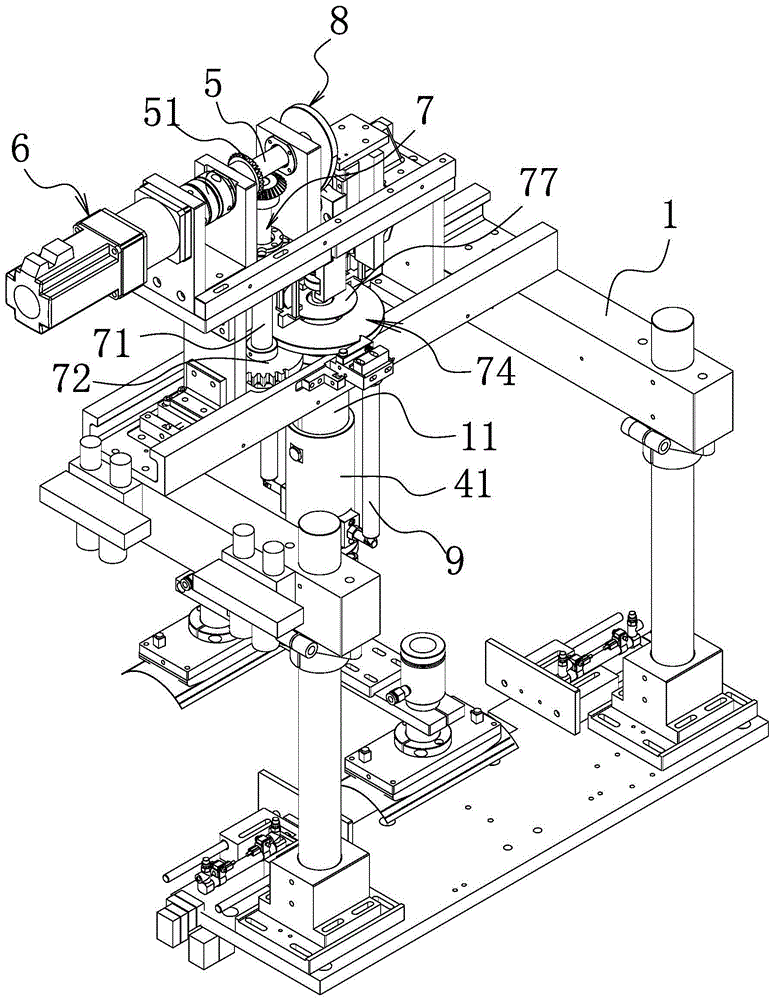
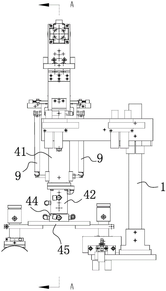
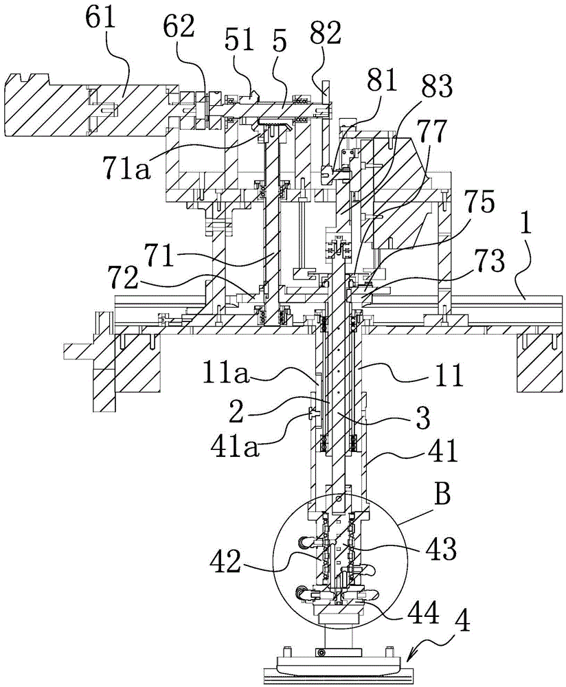
[0026] Such as Figure 1-3 As shown, the cam rotary feeding device includes a mounting bracket 1, and the mounting bracket 1 includes a mounting portion and a cantilever portion connected to the mounting portion. On the mounting bracket 1, there is a cylindrical rotating shaft 2 which is vertically arranged and can rotate relative to the mounting bracket 1. In the cylindrical rotating shaft 2, there is a cylindrical rotating shaft 2 which rotates synchronously with the cylindrical rotating shaft 2 and can rotate along the cylindrical rotating shaft 2. The lifting shaft 3 that lifts axially, the two ends of the lifting shaft 3 are respectively extended to the two ends of the cylindrical rotating shaft 2, and at least one is arranged along the axial direction of the cylindrical rotating shaft 2 on the inner wall of the cylindrical rotat...


PUM


Abstract

The invention relates to a rotary feeding device for a cam, and solves the problem of unreasonable design in the prior art. The rotary feeding device comprises a mounting bracket. A tubular rotating shaft, which is arranged vertically and can rotate relative to the mounting bracket, is arranged on the mounting bracket. A lifting shaft, which rotates with the tubular rotating shaft synchronously and can ascend and descend axially along the tubular rotating shaft, is arranged in the tubular rotating shaft. The two ends of the lifting shaft are lengthened outside the two ends of the tubular rotating shaft respectively. An executing manipulator, which rotates with the lifting shaft synchronously, is connected with the lower end of the lifting shaft. A driving shaft which is arranged horizontally and a driving mechanism which can drive the driving shaft to rotate are arranged on the mounting bracket. A rotary transmission mechanism, which can drive the tubular rotating shaft to rotate after the driving shaft rotates, is arranged between the tubular rotating shaft and the driving shaft. A cam transmission mechanism, which can drive the lifting shaft to ascend and descend after the driving shaft rotates, is arranged between the lifting shaft and the driving shaft. The rotary feeding device has the advantages of being more compact, low in cost and high in practicability.

Description

technical field [0001] The invention belongs to the technical field of mechanical equipment, in particular to a cam rotary feeding device. Background technique [0002] With the continuous development of social economy, automation equipment has gradually replaced the previous manual operation or semi-automatic processing equipment. In some cam rotary feeding device automation equipment, the manipulator is used to obtain or release products after lifting and rotating. At present, most of the existing cam rotary feeding devices have two power sources, one power source drives the rotation, and the other power source drives the lifting. Although this structure can meet the use requirements to a certain extent, it still has the following defects at least: 1. The structure is relatively complicated and the manufacturing cost is high, which virtually increases the use cost. 2. The equipment is large in size and heavy in weight. 3. The debugging process is cumbersome and difficul...

Claims


Application Information

Patent Timeline
Patent Type & Authority Applications(China)
IPC IPC(8): B65G47/91
CPCB65G47/91
Inventor 李国锋袁寒春蒋辛未
Owner TANAC AUTOMATION
Why Eureka
Try Eureka