Dust-separation anti-explosion lamp

An explosion-proof lamp and dust-proof technology, which is applied in the direction of gas-proof/water-proof devices, separation methods, lighting and heating equipment, etc., can solve the problems of ineffective prevention of explosion and heating on the surface of electrical equipment, and reduce the probability of dust explosions. The effect of reducing the probability of dust explosion and reducing the dust concentration

Active Publication Date: 2016-05-18
CHINA FEICE EXPLOSION PROOF
View PDF4 Cites 2 Cited by
  • Summary
  • Abstract
  • Description
  • Claims
  • Application Information

AI Technical Summary

Problems solved by technology

[0002] Explosion-proof lamps refer to lamps that take various specific measures to prevent the ignition of surrounding explosive mixtures such as explosive gas atmospheres, explosive dust atmospheres, gas gases, etc.; it is widely used in oil mining, oil refining, chemical industry, coal mines, railways, flood control, Dangerous environments such as military industry and offshore oil platforms, oil tankers and other places; common explosion-proof lamps are divided into flameproof lamps, increased safety lamps, composite lamps, etc. according to the structural type; there are two reasons for the ignition of flammable gas mixtures by electrical equipment: One is the sparks and arcs generated by electrical equipment, and the other is the heating on the surface of electrical equipment; traditional explosion-proof lights place equipment that is prone to arcs inside the explosion-proof shell, which can effectively prevent explosions, but in places with severe dust such as coal mines and flour mills This measure cannot effectively prevent explosions; dust explosions require three conditions: suitable dust concentration, sufficient air and oxidant, and sufficient temperature; therefore, breaking through the above conditions one by one can effectively prevent dust explosions

Method used


Image

  • Dust-separation anti-explosion lamp

Examples


Embodiment

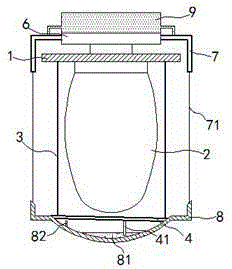
[0014] exist figure 1 In the shown embodiment, the dust-proof and explosion-proof lamp includes a base 1 and a lamp body 2; an explosion-proof curtain 3 made of a good heat-conducting material is wrapped around the periphery of the lamp body 2; the upper end of the explosion-proof curtain 3 is fixed On the base 1, the lower end of the explosion-proof curtain 3 is connected and sealed by an evaporation net 4; a drive turntable 6 is also installed on the base 1, and the drive turntable 6 is driven by a micro drive motor; A dust-proof cover 7 is installed on the drive turntable 6, and dust-proof wires 71 are evenly distributed circumferentially on the lower edge of the dust-proof cover 7; Dust-absorbing glue 81 is injected into the dust collection tray 8; the dust collection tray 8 is rotationally connected with the evaporation net 4; the angle between the evaporation net 4 and the two planes where the dust collection tray 8 is located is 3 -10 degrees; on the dust collection tr...


PUM


Abstract

The invention relates to a dust-separation anti-explosion lamp. the dust-separation anti-explosion lamp comprises a base and a lamp body; the periphery of the lamp body is wrapped with an anti-explosion curtain made of good heat conducting materials; the upper end of the anti-explosion curtain is fixed to the base, and the lower end of the anti-explosion curtain is connected and sealed through an evaporation net; a driving rotating disc is further mounted on the base and driven by a micro driving motor; a dust-separation cover is further mounted on the driving rotating disc, and dust-separation wires are evenly distributed on the lower edge of the dust-separation cover in the circumferential direction; the lower ends of the dust-separation wires are fixedly connected to a dust collecting disc; the dust collecting disc is rotatably connected with the evaporation net; and a water supplementing cavity is further fixedly mounted above the dust-separation cover, and liquid in the water supplementing cavity is communicated with the dust-separation cover and the dust-separation wires. The anti-explosion lamp is novel in structure, the temperature and the dust concentration around the lamp body can be effectively reduced, and the phenomenon that the lamp body induces dust explosion is completely eradicated in a more-insurance manner.

Description

technical field [0001] The invention relates to a lighting fixture, in particular to an explosion-proof lamp. Background technique [0002] Explosion-proof lamps refer to lamps that take various specific measures to prevent the ignition of surrounding explosive mixtures such as explosive gas atmospheres, explosive dust atmospheres, gas gases, etc.; it is widely used in oil mining, oil refining, chemical industry, coal mines, railways, flood control, Dangerous environments such as military industry and offshore oil platforms, oil tankers and other places; common explosion-proof lamps are divided into explosion-proof lamps, increased safety lamps, composite lamps, etc. according to the structural type; there are two reasons for the ignition of flammable gas mixtures by electrical equipment: One is the sparks and arcs generated by electrical equipment, and the other is the heating on the surface of electrical equipment; traditional explosion-proof lamps place equipment that i...

Claims


Application Information

Patent Timeline
Patent Type & Authority Applications(China)
IPC IPC(8): F21S8/00F21V29/70F21V31/00B01D47/00
CPCB01D47/00F21S8/00F21V31/005
Inventor 仲杏英
Owner CHINA FEICE EXPLOSION PROOF
Why Eureka
Try Eureka