Display device, display method, and display system

A technology for a display device and a display method, which is applied in the direction of instruments, polarizing elements, glasses/goggles, etc., can solve the problems of large thickness of smart glasses, which is not conducive to the thin and light design of smart glasses, and achieves the advantages of light and thin design and reduced thickness Effect

Inactive Publication Date: 2016-05-18
BOE TECH GRP CO LTD
View PDF5 Cites 9 Cited by
  • Summary
  • Abstract
  • Description
  • Claims
  • Application Information

AI Technical Summary

Problems solved by technology

[0004] However, the inventors of the present application found that in the display process of smart glasses in the prior art, the width of the imaging module 1' and the width of the image conversion module 2' need to be large

Method used


Image

  • Display device, display method, and display system
  • Display device, display method, and display system
  • Display device, display method, and display system

Examples


Embodiment 1

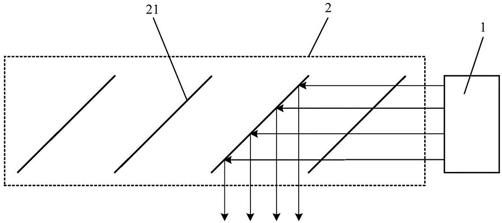
[0047] An embodiment of the present invention provides a display device, specifically, such as figure 2 As shown, the display device includes an imaging module 1 and an image conversion module 2, the image conversion module 2 includes n optical adjusters 21, n is a positive integer greater than or equal to 2, and the light emitted by each optical adjuster 21 along the imaging module 1 The direction of propagation is sequentially arranged on the side of the light-emitting surface of the imaging module 1 , the optical adjuster 21 farthest from the imaging module 1 can reflect light, and the other optical adjusters 21 can switch between reflecting light and transmitting light. Among them, the optical adjuster 21 farthest from the imaging module 1 can also be switched between reflective and transparent, or can only reflect light, as long as it can ensure that the optical adjuster 21 farthest from the imaging module 1 can reflect light. There is no limit. Of course, in order to e...

example 1

[0074] Such as Figure 10 As shown, the image conversion module 2 includes a plurality of micro-electro-mechanical systems, and when the mirrors included in each micro-electro-mechanical system reflect the light emitted by the imaging module 1, the mirrors included in the micro-electro-mechanical systems all have the same inclination angle, so that each micro-electro-mechanical system When the system reflects the light emitted by the imaging module 1, its adjustment effect on the light is the same. At this time, during the display process of the display device, one frame of image is divided into multiple sub-images along its width, and one frame time is divided into multiple sub-images. time period, a sub-image is displayed within a time period, so that all mirrors of other micro-electro-mechanical systems on the side of the micro-electro-mechanical system close to the imaging module 1 do not reflect the light emitted by the imaging module 1, corresponding to the sub-image All...

example 2

[0076] Such as Figure 11 and Figure 12 As shown, the image conversion module 2 includes a plurality of micro-electro-mechanical systems, one part of the micro-electro-mechanical systems is used to reflect the light emitted by the imaging module 1 to one observation point, and the other part of the micro-electro-mechanical systems is used to reflect the light emitted by the imaging module 1 to another One observation point, when the above one observation point and the other observation point are the user's left eye and the user's right eye respectively, the display device in the embodiment of the present invention not only has a small thickness, but also can realize naked-eye 3D display.

[0077] The following embodiments of the present invention give two specific examples to describe in detail how the above-mentioned display device realizes naked-eye 3D display:

[0078] Exemplarily, as Figure 11 and Figure 12 As shown, the image conversion module 2 includes a first mic...


PUM


Abstract

The invention discloses a display device, a display method, and a display system, and relates to the display technical field. According to the invention, the technical problems that the thickness of intelligent glasses is large and the thinning design of the intelligent glasses is not facilitated are solved. The display device includes an imaging module and an image transition module. The image transition module includes at least two optical regulators. The optical regulators are arranged at the light-out side of the imaging module in turn in the propagation direction of light emitted from the image module. The optical regulator which is farthest from the imaging module can reflect light, and other optical regulators can be switched between the reflection and light transmission. The display device, the display method, and the display system are applied to the virtual reality technology.

Description

technical field [0001] The present invention relates to the field of display technology, in particular to a display device, a display method and a display system. Background technique [0002] With the continuous development of science and technology, people's lives have entered the era of mobile Internet, and wearable devices with high portability have been widely favored by users. Among them, smart glasses are undoubtedly the pioneer of wearable devices, which completely subverted people's cognition of the functions of glasses in the past, and brought more entertainment experience to users while freeing users' hands. [0003] Such as figure 1 As shown, the smart glasses in the prior art include an imaging module 1' and an image conversion module 2' arranged on the side of the light-emitting surface of the imaging module 1', wherein the imaging module 1' is used to display images, and the image conversion module 2' For reflecting the image into the user's eyes, for exampl...

Claims


Application Information

Patent Timeline
IPC IPC(8): G02B27/01G02B26/08G02F1/1335
CPCG02B26/0833G02B27/0101G02F1/133528G02B2027/0178G02B26/08G02B2027/0134G02B2027/0138G02B27/0172G02F1/1347G02F1/13478G02F1/133555G02B5/30G02F1/133345G02F1/133553G02C7/12G02B5/26G02C7/14G02B5/201G02B5/20G02B5/28G02F1/133342G02F1/133557G02B27/0977G02F1/1343
Inventor 刘建涛李文波吕学文
Owner BOE TECH GRP CO LTD
Why Eureka
Try Eureka