Diversion nozzle material pull structure
A material handle and drainage groove technology, which is applied in the field of die-casting molds, can solve problems such as deformation, and achieve the effects of preventing deformation, firm and reliable connection, and stable molds
- Summary
- Abstract
- Description
- Claims
- Application Information
AI Technical Summary
Problems solved by technology
Method used
Image
Examples
Embodiment 1
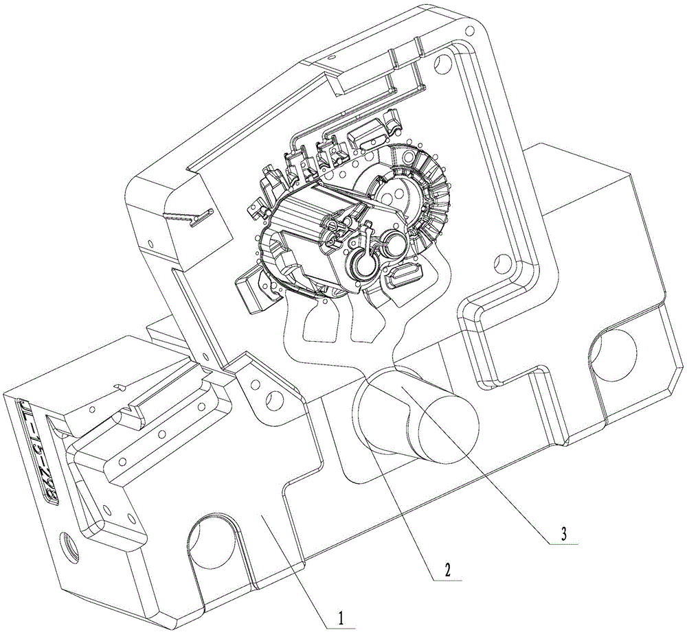
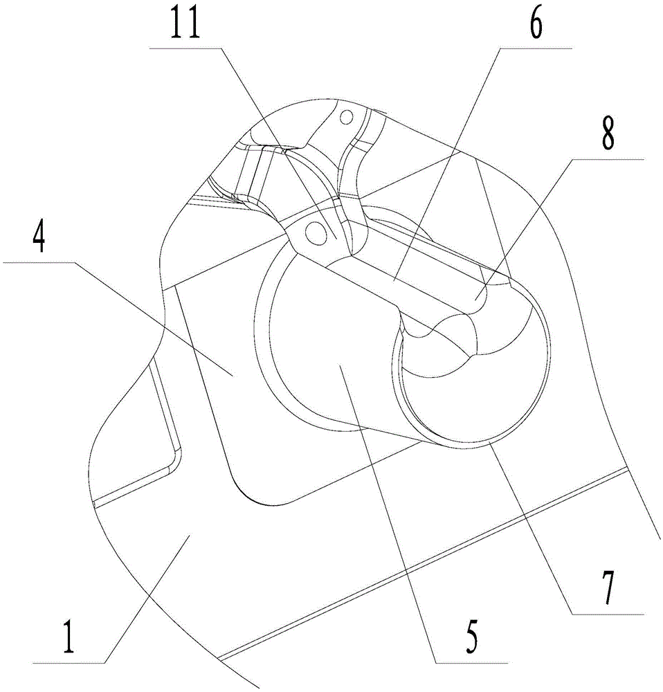
[0021] Embodiment 1: A kind of shunt nozzle pulling material structure (see attached figure 1 , attached figure 2 ), including the fixed mold frame 1, the shunt nozzle 2 installed on the fixed mold frame, the product material handle 3 is arranged between the shunt nozzle and the fixed mold frame, and the shunt nozzle includes a base 4 and a shunt nozzle arranged on the base The body 5 has a rectangular base, and the diverter nozzle is arranged vertically on the base. The body of the diverter nozzle is in the shape of a circular platform with a small upper part and a larger lower part. There is a drainage groove 6 on the side wall of the diverter nozzle body. There is a circle of holding groove 7 on the edge of the upper surface of the diversion nozzle body. Both ends of the holding groove are connected with the drainage groove. , the angle between the sides and the bottom of the holding groove is 88-92 degrees. The axial height of the holding groove from the upper surface o...
Embodiment 2
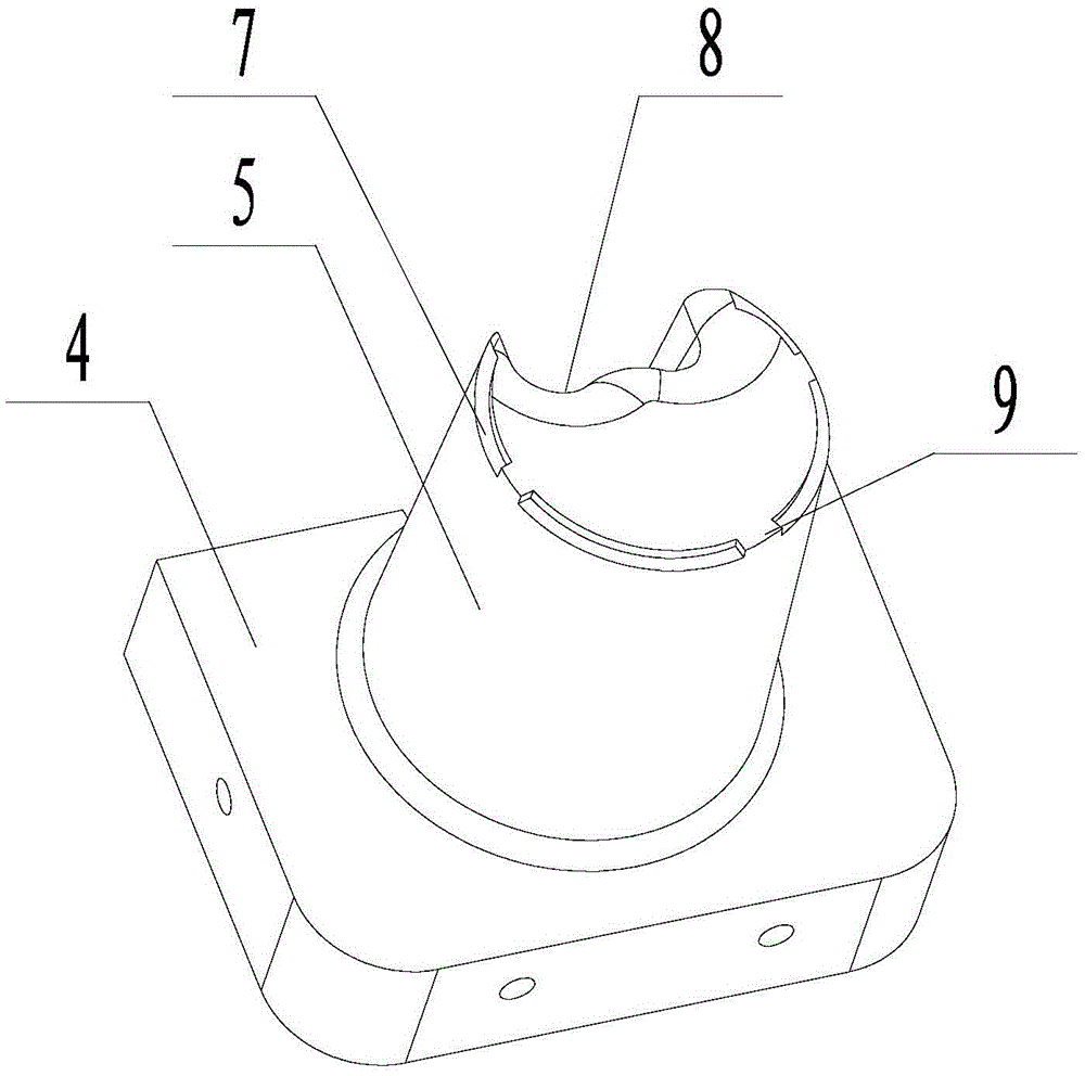
[0023] Embodiment 2: A kind of shunt nozzle pulling material structure (see attached image 3 ), including the fixed mold frame 1, the shunt nozzle 2 installed on the fixed mold frame, the product material handle 3 is arranged between the shunt nozzle and the fixed mold frame, and the shunt nozzle includes a base 4 and a shunt nozzle arranged on the base The body 5 has a rectangular base, and the diverter nozzle is arranged vertically on the base. The body of the diverter nozzle is in the shape of a circular platform with a small upper part and a larger lower part. There is a drainage groove 6 on the side wall of the diverter nozzle body. There is a circle of holding groove 7 on the edge of the upper surface of the diversion nozzle body. Both ends of the holding groove are connected with the drainage groove. , the angle between the sides and the bottom of the holding groove is 88-92 degrees. The axial height of the holding groove from the upper surface of the diverter body to...
Embodiment 3
[0024] Embodiment 3: A kind of shunt nozzle pulling material structure (see attached image 3 ), including the fixed mold frame 1, the shunt nozzle 2 installed on the fixed mold frame, the product material handle 3 is arranged between the shunt nozzle and the fixed mold frame, and the shunt nozzle includes a base 4 and a shunt nozzle arranged on the base The body 5 has a rectangular base, and the diverter nozzle is arranged vertically on the base. The body of the diverter nozzle is in the shape of a circular platform with a small upper part and a larger lower part. There is a drainage groove 6 on the side wall of the diverter nozzle body. There is a circle of holding groove 7 on the edge of the upper surface of the diversion nozzle body. Both ends of the holding groove are connected with the drainage groove. , the angle between the sides and the bottom of the holding groove is 88-92 degrees. The axial height of the holding groove from the upper surface of the diverter body to...
PUM
| Property | Measurement | Unit |
|---|---|---|
| height | aaaaa | aaaaa |
| width | aaaaa | aaaaa |
Abstract
Description
Claims
Application Information
 - R&D
- Intellectual Property
- Life Sciences
- Materials
- Tech Scout
- Unparalleled Data Quality
- Higher Quality Content
- 60% Fewer Hallucinations
Browse by: Latest US Patents, China's latest patents, Technical Efficacy Thesaurus, Application Domain, Technology Topic, Popular Technical Reports.
© 2025 PatSnap. All rights reserved.Legal|Privacy policy|Modern Slavery Act Transparency Statement|Sitemap|About US| Contact US: help@patsnap.com


