
Specified spiral photocatalysis sewage treatment equipment

A technology for sewage treatment and special equipment, which is applied in illumination water/sewage treatment, oxidized water/sewage treatment, special compound water treatment, etc., and can solve the problem of short photocatalytic distance

Inactive Publication Date: 2016-05-25
CHENGDU JINCHEN ENVIRONMENTAL TECH
View PDF0 Cites 2 Cited by
  • Summary
  • Abstract
  • Description
  • Claims
  • Application Information

AI Technical Summary

Problems solved by technology

[0004] Most of the existing tank-type photocatalytic sewage treatment equipment adopts the structure of inner tube and outer tube. The cavity formed between the transparent inner tube and the outer tube is used to fill the photocatalytic carrier, and the center of the inner tube is equipped with a lamp tube structure. The effective photocatalytic distance of this structure is short, requiring multiple devices to work in series or in parallel

Method used


Image

  • Specified spiral photocatalysis sewage treatment equipment
  • Specified spiral photocatalysis sewage treatment equipment
  • Specified spiral photocatalysis sewage treatment equipment

Examples


Embodiment 1

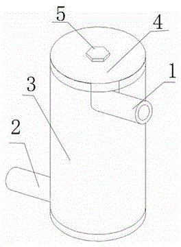
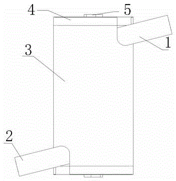
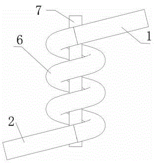
[0022] A spiral photocatalytic sewage treatment special equipment, comprising a pipe body 3, end caps 4 screwed on both ends of the pipe body 3, a spiral glass tube 6 is arranged inside the pipe body 3, the water inlet 1 and the water outlet 2 of the spiral glass tube 6 Lead out through the opening 8 provided on the tube body 3, the center of the spiral glass tube 6 is provided with a lamp tube 7, the inner wall of the tube body 3 is a glass reflective surface 31, the spiral glass tube 6 is provided with activated carbon, and TiO2 is attached to the activated carbon . The inner wall of the tube body 3 adopts a glass reflective surface, so that the light emitted by the lamp tube 7 passes through the gaps between the spiral glass tubes 6 and is reflected to the backlight surface of the spiral glass tube 6, increasing the irradiated surface of the spiral glass tube and improving the efficiency. The end cap 4 is provided with a hexagonal nut 5 . Easy removal of end caps. The di...

Embodiment 2

[0025] A spiral type special equipment for photocatalytic sewage treatment, comprising a pipe body 3, end caps 4 screwed on both ends of the pipe body 3, a spiral plexiglass tube 6 is arranged inside the pipe body 3, the water inlet 1 and the outlet of the spiral plexiglass tube 6 The nozzle 2 is led out through the opening 8 provided on the tube body 3, the center of the spiral plexiglass tube 6 is provided with a lamp tube 7, the inner wall of the tube body 3 is a glass reflective surface 31, and the spiral plexiglass tube 6 is provided with activated carbon, activated carbon TiO2 is attached to it. The inner wall of the tube body 3 adopts a glass reflective surface, so that the light emitted by the lamp tube 7 passes through the gap between the spiral plexiglass tubes 6 and then reflects to the backlight surface of the spiral plexiglass tube 6, increasing the irradiated surface of the spiral plexiglass tube) , which improves the efficiency. The end cap 4 is provided with a...


PUM

PropertyMeasurementUnit
diameteraaaaaaaaaa
diameteraaaaaaaaaa

Abstract

The invention relates to specified spiral photocatalysis sewage treatment equipment, relating to the technical field of transportation and loading equipment. The specified spiral photocatalysis sewage treatment equipment comprises a tube body (3) and end covers (4), wherein the end covers (4) are fixed to two ends of the tube body (3) in a threaded manner. The specified spiral photocatalysis sewage treatment equipment is characterized in that a spiral glass tube (6) is arranged in the tube body (3), wherein a water inlet (1) and a water outlet (2) of the spiral glass tube (6) are led out through an opening (8) formed in the tube body (3); a lamp tube (7) is arranged in the center of the spiral glass tube (6); the inner wall of the tube body (3) is a glass reflection surface (31); the spiral glass tube (6) is filled with activated carbon; and TiO2 is attached to the activated carbon.

Description

technical field [0001] The invention relates to the technical field of transportation equipment, and provides a special spiral photocatalytic sewage treatment equipment. Background technique [0002] Water is an important factor for economic development and sustainable social development. With the development of industry and the continuous expansion of urban scale, water pollution has become a big problem. Urban sewage is an important reason for the pollution of rivers and lakes, and one of the main reasons for restricting the sustainable development of many cities. How to control the pollution of the water environment while the economy is developing at a high speed, so as to realize the goal of scientific and harmonious development of social economy is an important problem to be solved urgently in our country. [0003] Photocatalytic oxidation is a water treatment technology that has only appeared in the past 20 years. It can usually completely mineralize organic matter i...

Claims


Application Information

Patent Timeline
Patent Type & Authority Applications(China)
IPC IPC(8): C02F1/30C02F1/74
CPCY02W10/37C02F1/30C02F1/74C02F2305/10
Inventor 陈全涛
Owner CHENGDU JINCHEN ENVIRONMENTAL TECH
Learn More