Cell culture sedimentation device

A settling device and cell culture technology, applied in the field of machinery, can solve the problems of difficulty in magnification and blockage of rotating screen cells, and achieve the effects of convenient and reliable operation and easy magnification.

Active Publication Date: 2018-12-07
上海保兴生物设备工程有限公司
View PDF5 Cites 0 Cited by
  • Summary
  • Abstract
  • Description
  • Claims
  • Application Information

AI Technical Summary

Problems solved by technology

In the prior art, the free cell culture uses a rotating screen, but the rotating screen is easily blocked by cells; the microcarrier cell culture often uses a sedimentation column, but it is difficult to scale up after the sedimentation column is placed in a stainless steel cell tank

Method used


Image

  • Cell culture sedimentation device
  • Cell culture sedimentation device
  • Cell culture sedimentation device

Examples


Embodiment 1

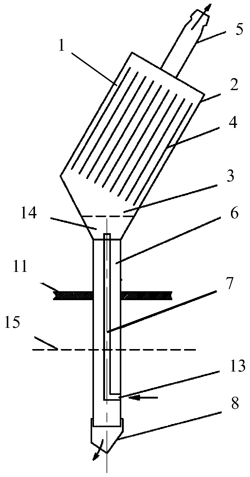
[0019] like figure 1 and figure 2 As shown, the cell culture settling device of the present invention includes a container 1, wherein the container 1 includes a settling chamber 2 and a transition chamber 3, the settling chamber 2 is provided with a settling unit 4, and the upper part of the container 1 is provided with a The liquid collection pipe 5, the liquid collection pipe 5 communicates with the upper part of the settling chamber 2, the transition chamber 3 is connected to the bottom of the settling chamber 2, the diameter of the transition chamber 3 decreases from top to bottom, and the lower end of the container 1 is connected with an outer pipe 6. The upper end of the outer tube 6 communicates with the transition cavity 3, and an inner tube 7 is arranged inside the outer tube 6. There is a gap between the outer wall of the inner tube 7 and the inner wall of the outer tube 6, and the upper end of the inner tube 7 extends to the transition cavity 3 and communicates w...

Embodiment 2

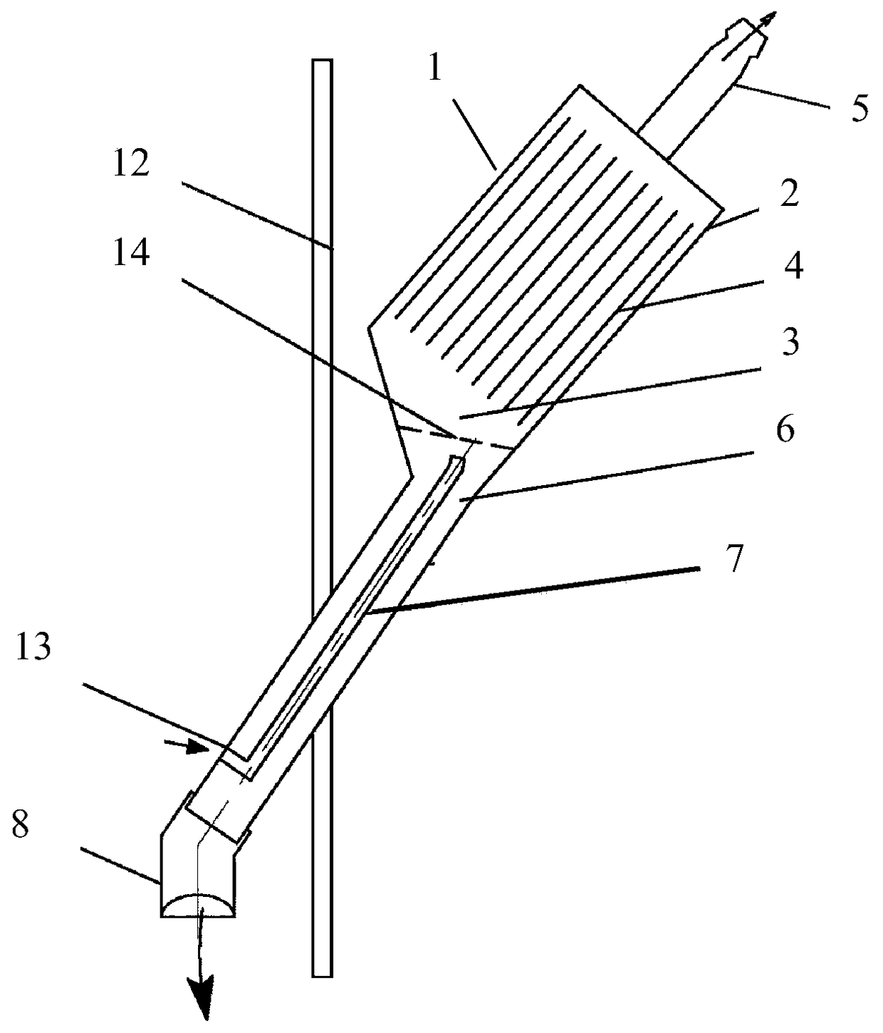
[0027] like image 3 and Figure 4 As shown, the outer tube 6 is fixedly arranged in the side wall of a tank body 12, the outer wall of the outer tube 6 is connected to the side wall of the tank body 12, and the axial direction of the outer tube 6 is 10-50 degrees to the axial direction of the tank body 12. The included angle is , the container 1 is located outside the tank body 12 and above the connection between the outer tube 6 and the tank body 12 .

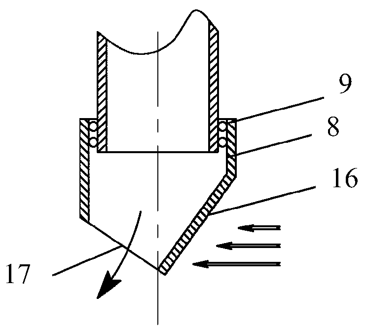
[0028] Further, the end tube 8 has a bend of 100-170 degrees in the axial direction.

[0029] The specific working principle of Embodiment 2 is: the outer tube 6 is fixed on the side of the tank body 12 . The liquid collection pump lifts the culture solution 15 in the tank into the transition chamber 3 through the end tube 8, the outer tube 6 and the inner tube 7. Under the action of the slope at the outlet of the end tube 8, a negative pressure is generated at the outlet of the end tube 8. When the liquid level 14 in the...


PUM


Abstract

A cell culture sedimentation device comprises a sedimentation cavity and a transition cavity, wherein a sedimentation unit is arranged in the sedimentation cavity; a liquid collecting pipe is arranged at the upper part of the sedimentation cavity; the transition cavity is connected to the bottom of the sedimentation cavity; the drift diameter of the transition cavity decreases from top to bottom; the lower end of the transition cavity is connected with an outer tube; an inner tube is arranged in the outer tube; the lower end of the outer tube is sleeved by a tail end tube; an outlet is formed in the lower end of the tail end tube; the axial directions of the outlet and the outer tube form an included angle of 100-170 degrees. According to the invention, negative pressure is formed at one inlet through pressure difference between two inlets of the two sleeved tubes, continuous cycle of a liquid between the two sleeved tubes is realized by virtue of the negative pressure, in the continuous cycle process, cells or micro carriers, which are subsided by the sedimentation unit in the sedimentation cavity, return to a tank body under the gravity action to realize sedimentation separation. The cell culture sedimentation device can be mounted at the upper part or on the side surface of a tank lid, so that easy amplification is realized; the liquid can be conveyed without additional pipelines and pumps, and in-place high-pressure sterilization operation is convenient and reliable.

Description

Technical field: [0001] The invention relates to the field of machinery, in particular to biomachines for culturing cells, in particular to a cell culture sedimentation device. Background technique: [0002] Animal cell culture technology is widely used in scientific research and production in the field of biomedicine. In order to increase the cell density, it is necessary to add medium during the cultivation process, and the cells are separated by a certain device and left in the tank. Since animal cells are not protected by cell membranes and are very sensitive to external forces, they cannot be separated by centrifugation. In the prior art, free cell culture uses a rotating screen, but the rotating screen is easily blocked by cells; microcarrier cell culture often uses a sedimentation column, but it is difficult to scale up after the sedimentation column is placed in a stainless steel cell tank. Invention content: [0003] The object of the present invention is to prov...

Claims


Application Information

Patent Timeline
Patent Type & Authority Patents(China)
IPC IPC(8): C12M1/00C12M3/02
Inventor 王国政干燕戚良华吴忠杰
Owner 上海保兴生物设备工程有限公司
Why Eureka
Try Eureka