
A continuous phenol extraction system, a polycarbonate resin production system including the same, and a production method
A polycarbonate resin and production system technology, applied in separation methods, chemical instruments and methods, preparation of organic compounds, etc., can solve the problems of not working well, increasing equipment investment, reducing equipment use efficiency, etc., and reducing cleaning The use of chemical agents, the effect of reducing heat transfer efficiency and improving production efficiency
- Summary
- Abstract
- Description
- Claims
- Application Information
AI Technical Summary
Problems solved by technology
Method used
Image

Examples
Embodiment 1
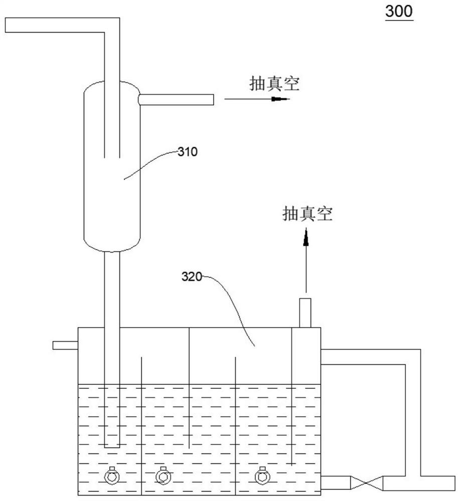
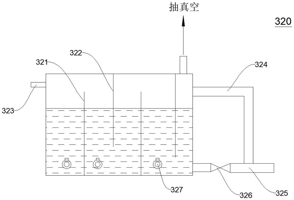
[0113] This embodiment provides a phenol continuous extraction system 300, the phenol continuous extraction system 300 is as follows figure 1 Shown includes a gas-liquid separation unit 310 and a phenol collection unit 320 in communication.
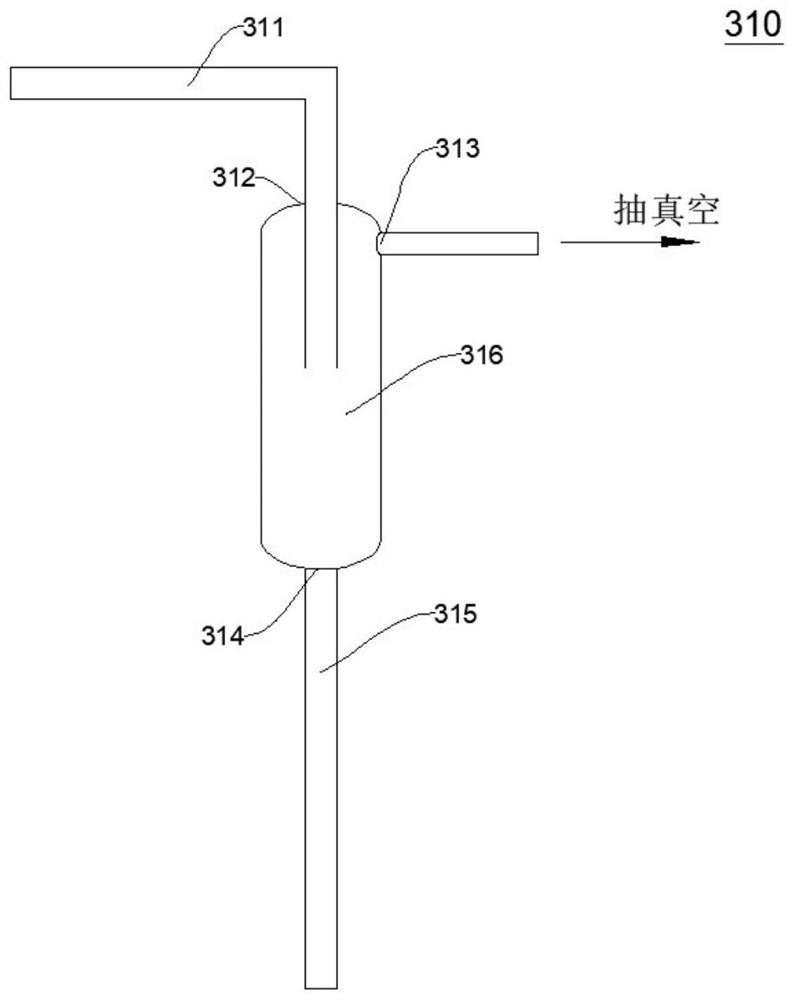
[0114] The specific structure of the gas-liquid separation device 310 is as follows: figure 2 As shown, it includes a separation device housing, the housing is provided with a feed port 312, an exhaust port 313 and a liquid discharge port 314, the liquid discharge port 314 is connected to the liquid discharge pipeline 315, and the cleaning liquid is filled in the phenol collection device 320. The outlet end of the liquid discharge pipeline 315 extends below the liquid level of the cleaning liquid, and the exhaust port 313 is externally connected with a vacuum device. A separation chamber 316 is formed inside the housing of the separation device. The diameter of the separation chamber 316 is larger than the diameter of the feed port 312 ...
Embodiment 2
[0119] The difference between this embodiment and Embodiment 1 is that the ratio of the cavity diameter of the gas-liquid separation chamber 316 to the caliber of the feed port 312 is 30:1, and other structures, positional relationships and connection methods of the device system are the same as in Embodiment 1. .
Embodiment 3
[0121] The difference between this embodiment and Embodiment 1 is that the ratio of the cavity diameter of the gas-liquid separation chamber 316 to the caliber of the feed port 312 is 50:1, and other structures, positional relationships and connection methods of the device system are the same as in Embodiment 1. .
PUM
 Abstract
Description
Claims
Application Information