Supercharge Your Innovation With Domain-Expert AI Agents!

Cut-off knife mechanism of leather cutting machine and leather cutting machine

A cutting machine and genuine leather technology, applied in leather punching/punching/cutting, small raw leather/big raw leather/leather/fur treatment, small raw leather/big raw leather/leather/fur mechanical treatment, etc., can solve production and assembly Problems such as high cost, complex structure of vibrating knife, high cost of motor drive mechanism, etc. achieve the effect of simplifying structure and reducing production cost

Inactive Publication Date: 2016-05-25
长园和鹰科技(河南)有限公司
View PDF7 Cites 4 Cited by
  • Summary
  • Abstract
  • Description
  • Claims
  • Application Information

AI Technical Summary

Problems solved by technology

[0004] But at present, whether it is an ordinary cutting machine or a CNC cutting machine, when cutting cloth, especially leather and other materials, the material is generally cut by a vibrating knife. The main working method is to drive the vibrating knife head continuously through a transmission mechanism such as a motor. The up and down reciprocating motion of the knife head can realize the cutting of the leather material, but because the structure of the vibrating knife is very complicated, its production and assembly costs are too expensive, especially in order to realize the high-frequency reciprocating motion of the knife head, its motor drive The cost of the machine transmission mechanism is even higher

Method used


Image

  • Cut-off knife mechanism of leather cutting machine and leather cutting machine
  • Cut-off knife mechanism of leather cutting machine and leather cutting machine
  • Cut-off knife mechanism of leather cutting machine and leather cutting machine

Examples


Embodiment Construction

[0029] In order to make the object, technical solution and advantages of the present invention clearer, various embodiments of the present invention will be described in detail below in conjunction with the accompanying drawings. However, those of ordinary skill in the art can understand that, in each implementation manner of the present invention, many technical details are provided for readers to better understand the present application. However, even without these technical details and various changes and modifications based on the following implementation modes, the technical solution claimed in each claim of the present application can be realized.

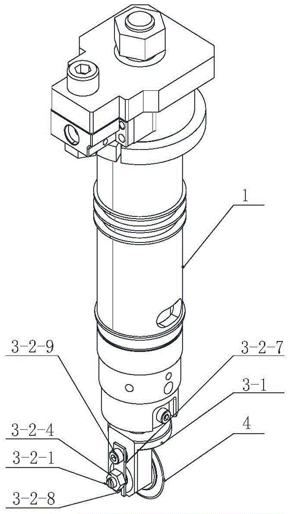
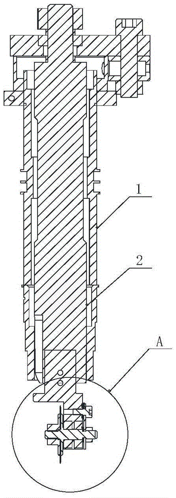
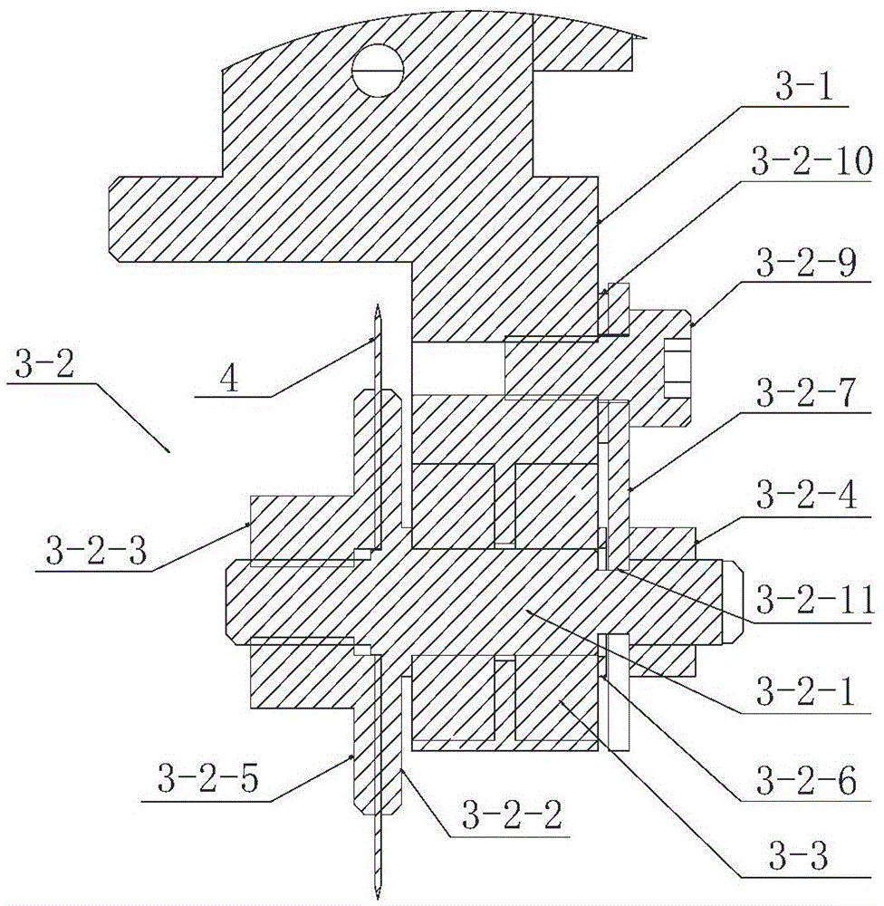
[0030] The first embodiment of the present invention relates to a cutting knife mechanism of a leather cutting machine, such as figure 1 and figure 2 As shown, the cutter mechanism is mainly composed of the cutter body, the handle 1 arranged on the machine head, the first driving device (not shown in the figure) that drive...


PUM


Abstract

The invention relates to a cut-off knife mechanism of a leather cutting machine. The cut-off knife mechanism comprises a cut-off knife body, a knife handle, a first driving device, a second driving device, a knife bar and a locking assembly, wherein the knife handle is arranged on a machine head, the first driving device drives the knife handle to conduct rotation motion, the second driving device drives the knife handle to conduct lifting motion, the knife bar is arranged in the knife handle and coaxially fixed with the knife handle, and the locking assembly is connected with the knife bar and fixes the cut-off knife body; the cut-off knife body is a circular knife, the locking assembly comprises a supporting part connected with the knife bar and a locking part which is matched with the supporting part and conducts locking on the circular knife, the locking part is provided with a hinge pin which penetrates through the supporting part and is connected with the circular knife, an empty sleeve is formed between the supporting part and the hinge pin, and when the circular knife rotates, the hinge pin rotates along with the circular knife. Compared with the prior art, due to the fact that when leather is cut by the circular knife, the leather is cut in a passive rotation mode, control of a motor transmission part over the circular knife can be omitted; normal cutting is guaranteed, the structure of the whole cut-off knife mechanism can be simplified, and therefore the production cost of the whole machine is reduced.

Description

technical field [0001] The invention relates to the technical field of numerical control cutting, in particular to a knife mechanism of a leather cutting machine and the leather cutting machine. Background technique [0002] At present, in some leather cutting, cloth cutting and other industries, materials are often cut according to the needs of production, and modern people have higher and higher requirements for cutting technology, and high-speed efficiency is also required while pursuing high-quality cutting. For example, cutting out different shapes, different angles, and different lengths of cloth or leather requires manual cutting by workers in many cases. It is difficult to guarantee the quality of cutting, and the efficiency is relatively low. Therefore, in order to overcome this defect, the cutting machine was born And born. [0003] As a precision instrument for cutting materials such as cloth and leather, the cutting machine has been widely used in some leather a...

Claims


Application Information

Patent Timeline
Patent Type & Authority Applications(China)
IPC IPC(8): C14B5/00B26D1/16
CPCB26D1/165C14B5/00C14B2700/113
Inventor 尹智勇
Owner 长园和鹰科技(河南)有限公司
Features
  • R&D
  • Intellectual Property
  • Life Sciences
  • Materials
  • Tech Scout
  • Unparalleled Data Quality
  • Higher Quality Content
  • 60% Fewer Hallucinations
Learn More