
Floating-type device for rock embedment mounting of steel pipe pile in water and construction method thereof

A floating device, steel pipe pile technology, applied in the direction of support device, sheet pile wall, earthwork drilling, etc., can solve the problems of poor construction stability, inability to carry out work, limited space, etc.

Active Publication Date: 2016-05-25
SHANGHAI CIVIL ENG GRP FIFTH
View PDF4 Cites 3 Cited by
  • Summary
  • Abstract
  • Description
  • Claims
  • Application Information

AI Technical Summary

Problems solved by technology

[0002] The construction of drilling steel pipe pile holes in rocks and soil layers in water is a complicated and cumbersome process. At present, ship-type construction platforms are generally used for this construction, but the existing ship-type construction platforms have poor construction stability and floating. , the construction quality is difficult to control; and construction on some narrow and long rivers, due to the limited space, often faces the dilemma that the construction machinery on the ship-type construction platform cannot be arranged, resulting in low work efficiency and even the work cannot be carried out, so the construction period cannot be met.

Method used


Image

  • Floating-type device for rock embedment mounting of steel pipe pile in water and construction method thereof
  • Floating-type device for rock embedment mounting of steel pipe pile in water and construction method thereof
  • Floating-type device for rock embedment mounting of steel pipe pile in water and construction method thereof

Examples


Embodiment Construction

[0032] Below in conjunction with accompanying drawing, the present invention will be further described.

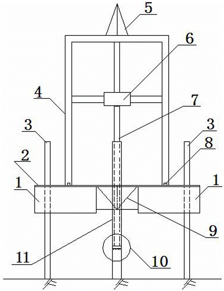
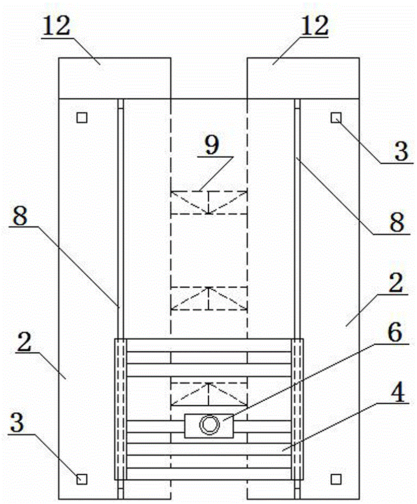
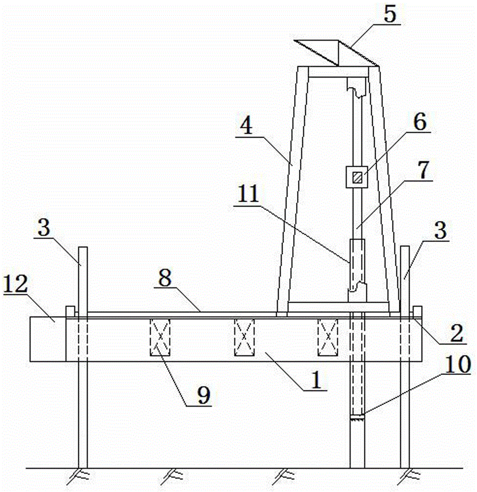
[0033] figure 1 Shown is a schematic view of the structure of the present invention, figure 2 shown, is figure 1 The schematic diagram of the top view structure, image 3 shown, is figure 1 The structure schematic diagram of the left view, as can be seen from the figure, the present invention comprises: pontoon 1, platform 2, hydraulic support column 3 and door frame 4. Among them, on both longitudinal sides below the platform 2, buoyancy tanks 1 are fixedly connected at intervals, and between the buoyancy tanks 1, several groups of trusses 9 are fixed at transverse intervals. The two ends of each truss 9 are respectively fixedly connected with the pontoon 1 on both sides; the platform 2 and the pontoon 1 are connected as a whole through the truss 9. The specific method is: the truss 9 is welded between the pontoon 1 at intervals, first The two buoyant tanks 1 and th...


PUM


Abstract

The invention discloses a floating-type device for the rock embedment mounting of a steel pipe pile in water. The floating-type device for the rock embedment mounting of the steel pipe pile in the water comprises a platform, and also comprises floating boxes, multiple groups of trusses, four hydraulic supporting columns, two tracks, a portal frame, a lifting mechanism and a drilling mechanism, wherein the floating boxes are longitudinally arranged fixedly on the two sides of the lower surface of the platform at an interval; the multiple groups of trusses are fixedly connected with the floating boxes on the two sides and are transversely arranged at an interval; the four hydraulic supporting columns are arranged at the four corners of a panel of the platform, and further, the upper ends of the four hydraulic supporting columns penetrate through the platform and the lower ends of the four hydraulic supporting columns are inserted into the water to a surficial rock; the two tracks are arranged on the platform, are parallel to each other and longitudinal and are further perpendicular to the two ends of the platform; the portal frame is arranged on the two tracks and can be moved along the tracks; the lifting mechanism is arranged on a transverse beam of the portal frame and is used for lifting to convey a steel pipe for position alignment; the drilling mechanism is fixedly arranged on a central beam of the portal frame. A construction method of the floating-type device for the rock embedment mounting of the steel pipe pile in the water comprises the following steps of performing position alignment; lifting a steel-pipe-pile pile casing, and enabling a drill rod to penetrate into the steel-pipe-pile pile casing; punching. The floating-type device which is provided by the invention is high in bearing capacity, is convenient to move, can be used for preventing the platform from being influenced by wave impact and a drilling dynamic load to generate shake, further, is simple in structure, easy and feasible to operate, and is applicable to various waterborne operations.

Description

technical field [0001] The invention relates to a construction facility, in particular to a floating device capable of drilling steel pipe pile holes in rocks and soil layers in water to realize the installation of steel pipe piles and a construction method thereof. Background technique [0002] The construction of drilling steel pipe pile holes in rocks and soil layers in water is a complicated and cumbersome process. Currently, ship-type construction platforms are generally used for this construction. However, the existing ship-type construction platforms have poor construction stability and floating. , the construction quality is difficult to control; and construction on some narrow and long rivers, due to the limited space, often faces the dilemma that the construction machinery on the ship-type construction platform cannot be arranged, resulting in low work efficiency and even the work cannot be carried out, so the construction period cannot be met. . Contents of the ...

Claims


Application Information

Patent Timeline
Patent Type & Authority Applications(China)
IPC IPC(8): E02D7/28E21B15/02
CPCE02D7/28E02D2250/0076E21B15/02
Inventor 项进唐俊徐荣会黄忠睦覃毅
Owner SHANGHAI CIVIL ENG GRP FIFTH
Learn More