
A method of eliminating the suction vortex of the water inlet of the pumping station under the condition of the in-line layout of the gate station

A technology for water inlets and pumping stations, applied in pumping stations, hydraulic models, water supply devices, etc., can solve problems such as strong vibration of water pump units and threats to the safe and stable operation of pumping stations, and achieve easy popularization and application, low cost and low investment Effect

Active Publication Date: 2017-05-24
YANGZHOU UNIV
View PDF6 Cites 0 Cited by
  • Summary
  • Abstract
  • Description
  • Claims
  • Application Information

AI Technical Summary

Problems solved by technology

Under the condition that the gates and stations are arranged in a straight line, the flow state of the water inlet during the operation of the pumping station will be more or less affected by the lateral flow velocity of the incoming river, which may generate a suction vortex that can bring a large amount of air into the pump, resulting in The water pump unit produces strong vibration, which threatens the safe and stable operation of the pump station

Method used


Image

  • A method of eliminating the suction vortex of the water inlet of the pumping station under the condition of the in-line layout of the gate station
  • A method of eliminating the suction vortex of the water inlet of the pumping station under the condition of the in-line layout of the gate station
  • A method of eliminating the suction vortex of the water inlet of the pumping station under the condition of the in-line layout of the gate station

Examples


Embodiment

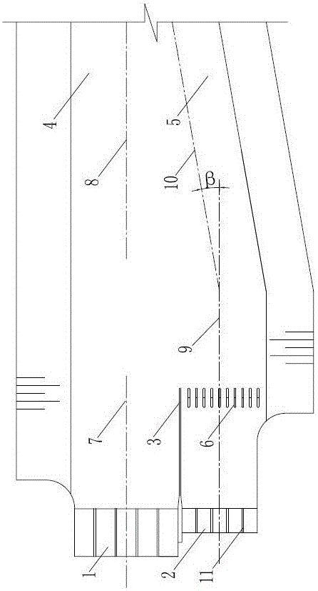
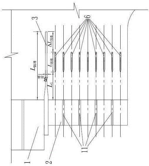
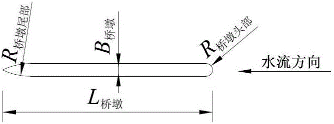
[0070] like Image 6 As shown in the figure, a pumping station hub adopts a parallel arrangement of gates and stations. The pumping station 2 of the pumping station hub is equipped with 5 sets of vertical axial flow pump units, and the diameter of the pump impeller is D. 0 The length of the pumping station 2 is 24.5m in the downstream direction, the width in the vertical direction is 38.9m, and the angle between the centerline 9 of the pumping station and the centerline 10 of the diversion river is β=10°. The control gate 1 of the pumping station hub is divided into 5 holes, each hole has a net width of 10m, the length of the gate body along the water flow direction is 24.5m, and the width in the vertical water flow direction is 53.6m. According to the needs of the structural arrangement of the cleaning machine bridge, the length and width of the pier 12 of the originally designed cleaning machine bridge are 10m and 1m respectively.

[0071] The pier 12 of the cleaning machin...


PUM


Abstract

The invention discloses a method for eliminating an air suction vortex at a water inlet of a pumping station under the condition of an inline layout of gate stations, and belongs to the technical field of hydraulic engineering pumping stations. Its characteristics are: using the pier of the sewage cleaning machine bridge on the water inlet side of the pump station to contain the large swirling flow caused by the lateral flow velocity in the forebay of the pump station, so as to achieve the purpose of eliminating the suction vortex at the water inlet of the pump station; The purpose of the suction vortex, the cleaning machine bridge is arranged at 4D0 away from the inlet section of the pump station water inlet, the number of holes is twice the number of units in the pump station, and the center line of the pier is the same as the water inlet of the pump station. The center line of the partition pier is aligned in the plane direction; a partition wall is set between the control gate and the pump station; the position, length and width of the cleaning machine bridge and the length of the partition wall can be within a certain range. Adjust within. The invention can effectively eliminate the suction vortex of the water inlet of the pumping station under the condition that the gate and the station are arranged in a straight line, and has great significance for ensuring the safe and stable operation of the pumping station.

Description

technical field [0001] The invention belongs to the technical field of water conservancy engineering pumping stations, and in particular relates to a method for eliminating the suction vortex at the water inlet of the pumping station under the condition that the control gate and the pumping station are arranged in-line. Background technique [0002] The pumping station hub consisting of a pumping station and a control gate is widely used in the plain areas of my country. The control gate is mainly used to discharge a large amount of upstream floods during the flood season, and the pump station is used to pump the downstream water to the upstream irrigation during the dry season. The inline arrangement of gates and stations is one of the layouts of the pumping station hub. The channel of the station is diagonally intersected with the said channel. The advantages of this arrangement are that it occupies less land, saves investment, and has high operating efficiency. For the ...

Claims


Application Information

Patent Timeline
Patent Type & Authority Patents(China)
IPC IPC(8): E03B5/00E03B11/00E02B1/02
CPCE02B1/02E03B5/00E03B11/00
Inventor 陆林广陆伟刚徐磊练远洋施克鑫洪飞
Owner YANGZHOU UNIV
Learn More