Beam-column node connecting device for assembled steelwork

A beam-column joint and connecting device technology, applied in the direction of building structure and construction, can solve problems such as affecting construction speed and quality, affecting joint force performance, poor joint ductility, etc., and achieving the effect of improving assembly speed and quality.

Inactive Publication Date: 2016-05-25
迁安市金东顺防腐工程有限公司
View PDF5 Cites 19 Cited by
  • Summary
  • Abstract
  • Description
  • Claims
  • Application Information

AI Technical Summary

Problems solved by technology

[0003] The beam-column joint is the most important joint in the fabricated steel structure system, which directly affects the construction speed and the degree of assembly of the structure. Therefore, the beam-column joints should be connected with high-strength bolts that are easy to operate as much as possible, and the bolts should be arranged as far as possible. It is easy for workers to fasten on site. The beam-column joints used in the existing engineering examples have the following disadvantages: In the traditional beam-column fully welded joints, the upper and lower flanges of the beam and the web and the column are welded on site. Although this connection method is a rigid connection, However, the ductility of the joints is poor, brittle failure is prone to occur in earthquakes, and on-site welding is required, which greatly affects the construction speed and quality. It is not used in multi-story fabricated steel structures. At the same time, due to the large welding area, it is easy to generate large residual stress , affecting the mechanical performance of the node
In the traditional bolted and welded joint connection, the upper and lower flanges of the beam end are welded to the column on site, and the web at the beam end is bolted to the column through a shear plate. This connection method requires on-site welding, which greatly affects the construction speed and quality, and the construction The program is complex and it is not easy to achieve rigid connection

Method used


Image

  • Beam-column node connecting device for assembled steelwork
  • Beam-column node connecting device for assembled steelwork
  • Beam-column node connecting device for assembled steelwork

Examples


Embodiment Construction

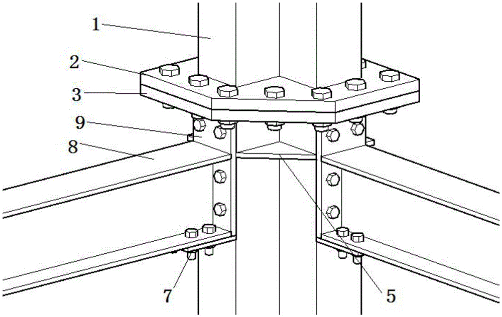
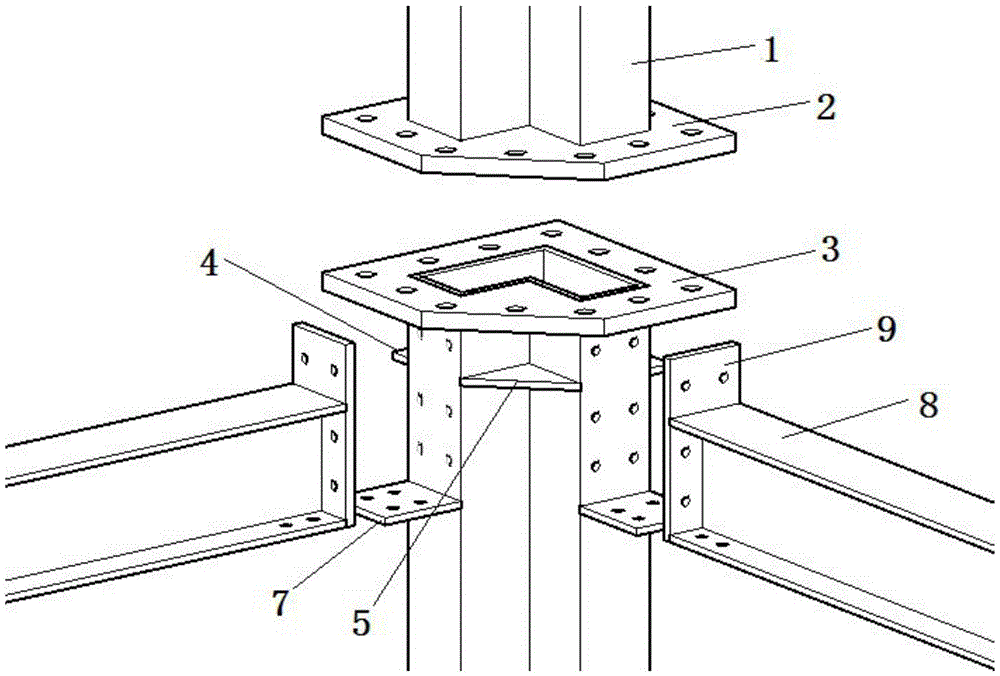
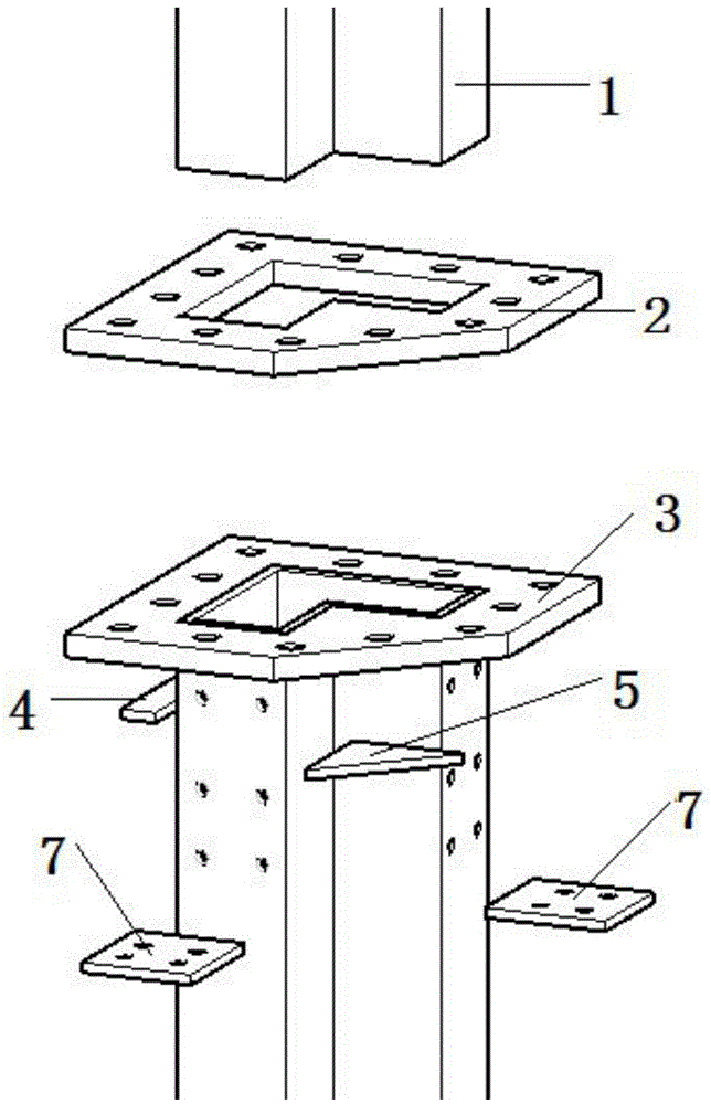
[0023] The present invention is described in detail below in conjunction with accompanying drawing:

[0024] as attached figure 1 , 2 As shown, the two column limbs of the lower column in the beam-column joint in the present invention are respectively connected with two beams by bolts, and the two column limbs of the L-shaped square pipe column in the end plate of the beam and the lower column are connected by bolts, and the H-shaped steel The lower flange of the beam and the supporting plate are connected by bolts; the flange at the top of the middle column of the lower column and the flange at the bottom of the middle column of the upper column are connected by bolts. The supporting plate in the lower column and the lower flange of the H-shaped steel beam have bolt holes with corresponding positions and the same size. The top flange and the column bottom flange have bolt holes with corresponding positions and the same size, and can be arranged in single or multiple rows of...


PUM


Abstract

The invention relates to a beam-column node connecting device for assembled steelwork and belongs to the technical field of structural engineering. The beam-column node connecting device comprises an upper column, a lower column and beams. Each of the upper and lower columns is manufactured in a factory through welding an L-shaped square tubular column, a column top ring flange, a column bottom ring flange, an external fin I, an external fin II, an internal fin and supporting plates, and each beam is manufactured in a factory through welding an H-shaped steel beam and an end plate; the form of the column is not limited to L-shaped square tubular columns, and other irregular columns or box-shaped columns can be selected. According to the beam-column node connecting device for the assembled steelwork, welding work is completely completed in the factories, assembling is carried out on site by adopting bolts, the work of bolt fastening is convenient and fast, and the speed and quality of construction are greatly improved, so that factory production and on-site rapid assembling are achieved.

Description

technical field [0001] The invention relates to a beam-column joint connecting device of a steel structure, which belongs to the technical field of structural engineering. Background technique [0002] At present, the systematic research on high-rise steel structure residences at home and abroad is in its infancy, and the innovation of industrially assembled high-rise steel structure systems is imperative. The prefabricated steel structure system refers to the building produced by manufacturing housing units or components according to uniform and standard building part specifications, and then transporting them to the construction site for assembly in place. It is characterized by light building weight, energy saving and environmental protection, fast construction speed, and high degree of industrialization. It can solve many problems such as the low level of construction industrialization in my country, low labor productivity in house construction, and low quality of tradit...

Claims


Application Information

Patent Timeline
Patent Type & Authority Applications(China)
IPC IPC(8): E04B1/24E04B1/58
CPCE04B1/24E04B1/2403E04B2001/2406E04B2001/2418
Inventor 刘学春詹欣欣周小俊张译文
Owner 迁安市金东顺防腐工程有限公司
Why Eureka
Try Eureka