Tyre six-component force testing device for eliminating unbalance loading

A test device and six-component force technology, which is applied in the direction of automobile tire testing, etc., can solve the problems of high-precision and large-range six-component force sensor, which are expensive, the measuring range cannot meet the requirements, and the tire load is large, so as to meet the mechanical characteristics test, The effect of simple and reasonable structure and low cost

Active Publication Date: 2016-05-25
柳州中动智轮科技有限公司
View PDF6 Cites 6 Cited by
  • Summary
  • Abstract
  • Description
  • Claims
  • Application Information

AI Technical Summary

Problems solved by technology

[0003] In the patent (CN102435449B), the six-component force sensor is installed on the side of the tire coaxial with the tire rotation axis, which can accurately measure the tire six-component force in the small-load tire contact footprint, but when measuring heavy-duty car tires or aviation tires , the tires have one thing in common - the load on the tire is very large
At this time, because there is a certain distance between the center of the tire contact footprint and the center of the six-component force sensor, and there is a moment arm between the tire vertical force and lateral force and the sensor center, the moment generated by the

Method used


Image

  • Tyre six-component force testing device for eliminating unbalance loading
  • Tyre six-component force testing device for eliminating unbalance loading
  • Tyre six-component force testing device for eliminating unbalance loading

Examples


Embodiment Construction

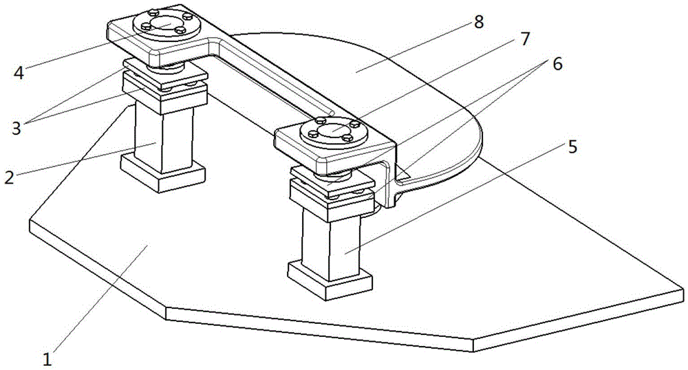
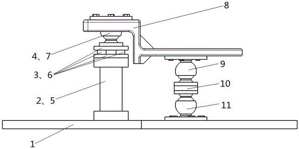
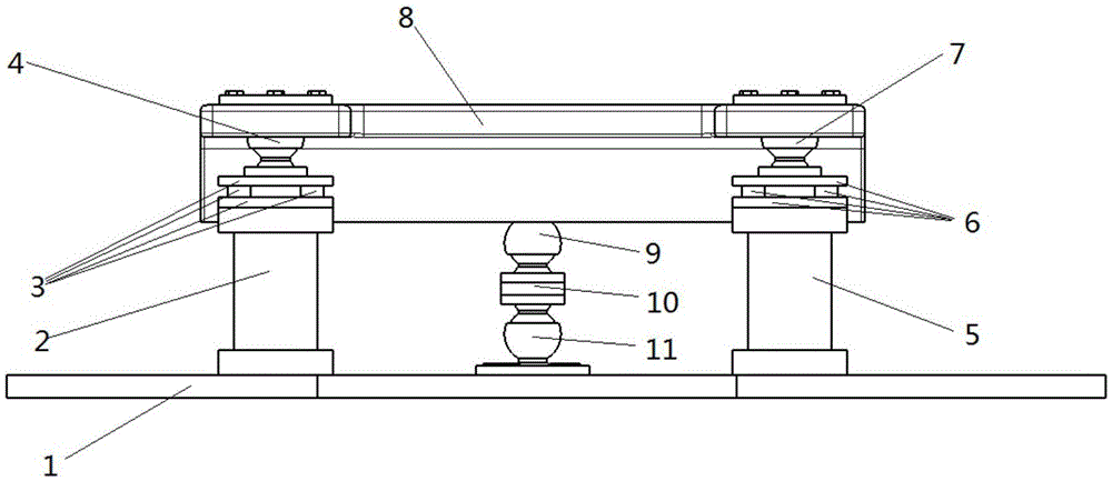
[0026] attached by figure 1 , 2 , shown in 3: the device includes base 1, pillar one 2, six-component force sensor one 3, ball joint one 4, pillar two 5, six-component force sensor two 6, ball joint two 7, bearing plate 8, ball joint three 9. Single component force sensor 10, ball joint four 11.

[0027] The upper end of the ball joint-4 is fixed on the bearing plate 8, the lower end of the ball joint-4 is fixed with the upper end of the six-component force sensor-3, the lower end of the six-component force sensor-3 is fixed on the pillar-2, and the pillar-2 is fixed on the On the base 1; the upper end of the ball joint 2 7 is fixed on the bearing plate 8, the lower end of the ball joint 2 7 is fixed to the upper end of the six-component force sensor 2 6, and the lower end of the six-component force sensor 2 6 is fixed on the pillar 2 5, the pillar Two 5 are fixed on the base 1.

[0028] The spherical hinge one 4 and the spherical hinge two 7 are symmetrically distributed i...


PUM


Abstract

The invention relates to a tyre six-component force testing device for eliminating unbalance loading, the device comprises a tyre, a simulated road, a tyre positioning loading mechanism, and also comprises a base, two pillars, two six-component force sensors, an one-component force sensor, four spherical hinges and a loading plate, wherein a first pillar (2) and a second pillar (5) are fixed to the base (1), a first six-component force sensor (3) and a second six-component force sensor (6) are respectively fixed to the first pillar (2) and the second pillar (5), the upper ends of a first spherical hinge (4) and a second spherical hinge (7) are fixedly connected with the lower surface of the loading plate (8), and the lower ends of the same are respectively fixedly connected with the first six-component force sensor (3) and the second six-component force sensor (6); the tyre positioning loading mechanism (13) is arranged on the loading plate (8); the upper end of a third spherical hinge (9) is fixed to the lower surface of the loading plate (8), the upper end of the one-component force sensor (10) is fixedly connected with the third spherical hinge (9), the lower end of the same is fixedly connected with a fourth spherical hinge (11), and the fourth spherical hinge (11) is fixed to the base (1). The tyre six-component force testing device of the present invention achieves the purpose of measuring the six-component force of a huge tyre by use of small-range sensors.

Description

technical field [0001] The invention relates to a tire mechanics testing device, in particular to a tire six-component force testing device for eliminating unbalanced loads. Background technique [0002] The six-component force of heavy-duty and large-load tires is the basis for the performance analysis and design of automobiles and aircraft. Its rolling dynamics performance - the six-component force characteristic affects the safety, handling stability, ride comfort and NVH performance of the car; affects the take-off of the aircraft , Landing, braking, turning and taxiing phases are related to the safety of automobiles and aircraft. The study of the six-component force characteristics is an important content of automobile tire dynamics and aircraft ground dynamics. [0003] In the patent (CN102435449B), the six-component force sensor is installed on the side of the tire coaxial with the tire rotation axis, which can accurately measure the tire six-component force in the sm...

Claims


Application Information

Patent Timeline
IPC IPC(8): G01M17/02
CPCG01M17/02
Inventor 卢荡敖策划
Owner 柳州中动智轮科技有限公司
Why Eureka
Try Eureka