
A free-form surface lens with high light extraction efficiency and its design method

A technology of curved lens and design method, which is applied in the fields of lens, optics, computing, etc. It can solve the problems of not considering the light output efficiency of the lens, and achieve the effect of simple design method, small loss of light energy and great flexibility

Active Publication Date: 2017-05-17
TIANJIN ZHONGHUAN ELECTRONICS LIGHTING TECH
View PDF3 Cites 0 Cited by
  • Summary
  • Abstract
  • Description
  • Claims
  • Application Information

AI Technical Summary

Problems solved by technology

However, the free-form surface lens designed by these methods is not designed in conjunction with the minimization of Fresnel energy loss, that is, the light extraction efficiency of the lens is not considered. The design method is particularly important

Method used


Image

  • A free-form surface lens with high light extraction efficiency and its design method
  • A free-form surface lens with high light extraction efficiency and its design method
  • A free-form surface lens with high light extraction efficiency and its design method

Examples


Embodiment 1

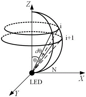
[0053] S1. In this embodiment, the XOZ plane is selected as the incident surface, the light source is located at the coordinate origin O, and the light distribution curve of the light source, that is, the spatial intensity distribution of the light energy of the light source is Lambertian. Divide the light energy emitted from the light source into N=200 parts, then each equally divided angle θ i Can be determined by the formula:

[0054]

[0055] Find

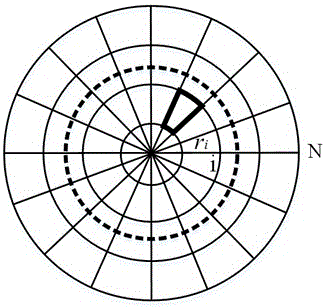
[0056] S2. In this embodiment, the shape of the illumination area is selected as a circle, the radius is R=100mm, the distance between the illumination area and the center of the LED is L=50mm, and the illuminance distribution is that all areas in the spot have equal illuminance. Then, the target surface 100 is also divided into N=200 parts according to the spot shape and illumination distribution requirements. Then the spot radius corresponding to each area can be calculated by the formula:

[0057]

[0058] Find

[0059] S3. In thi...

Embodiment 2

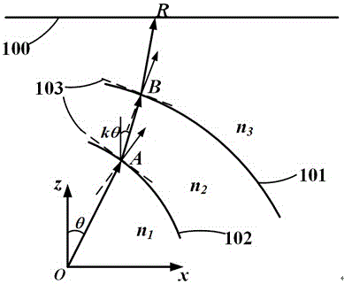
[0066] Repeat embodiment 1 with the same steps as described, the difference is that the free-form surface material in this embodiment is PC (polycarbonate), the height of the center point of the inner surface 102 is 5mm, and the height of the center point of the outer surface 101 is 8mm; The angular deflection coefficient of the inner surface 102 is k=1. The target surface is a circle with a radius of R=200mm, and the distance from the light source to the target surface 100 is L=100mm. Picture 9 The topography of the free-form surface lens of this embodiment, Picture 10 This is the illuminance distribution diagram of the free-form surface lens on the target surface 100 in this embodiment. After calculation, the uniformity of illumination is 0.94, the Fresnel optical loss is 9.8%, and the light extraction efficiency is 90.2%.


PUM


Abstract

The present invention relates to a free-form lens with high light emitting efficiency and a design method thereof. The free-form lens is semicircular. The bottom surface of the free-form lens is a conical recess. The semicircular surface of the free-form lens is an outer surface. The conical recess surface of the free-form lens is an inner surface. Two free-form surfaces are formed by the inner surface and the outer surface. The invention also discloses the design method of the free-form lens. The design method is simple, through the design of the inner and outer surface of the lens at the same time, the specific illumination type can be realized, since the inner and outer surface of the lens are free-form surfaces, the lens shape is optimized, the light energy loss of the lens can be minimized, thus the light emitted by an LED is projected to an illumination plane with high efficiency, since the material of the lens is an optically transparent material commonly used in the industry, the processing cost is low, and the lens is suitable for mass production.

Description

Technical field [0001] The invention belongs to LED packaging technology, relates to a free-form lens with high light extraction efficiency and a design method in LED packaging, and is particularly used in LED packaging to improve light efficiency, realize beam control, and meet different lighting requirements. Background technique [0002] Light Emitting Diode (LED, Light Emitting Diode) is a semiconductor light emitting device made based on the principle of electron-hole compound light emission. It has the advantages of high electro-optical conversion efficiency, long service life, environmental protection and energy saving, and small size. It is known as the 21st century Green lighting sources have been widely used in many fields and are considered by the industry to be the main development direction of future lighting technology and have huge market potential. [0003] Generally, in the high-power white light LED package, an indispensable part is the optical lens. The function...

Claims


Application Information

Patent Timeline
Patent Type & Authority Patents(China)
IPC IPC(8): G02B3/02G02B27/00G06F17/50H01L33/58
CPCG02B3/02G02B27/0012G06F30/17H01L33/58
Inventor 李春峰罗小兵谢斌边盾
Owner TIANJIN ZHONGHUAN ELECTRONICS LIGHTING TECH
Learn More