
Method and station for the construction of a stator winding with rigid bars for a rotary electrical machine

A technology of rotating electric machines and construction methods, which is applied in the manufacture of motor generators, electric components, electrical components, etc., and can solve the problems of discarding corresponding rods, increasing production costs, and reducing tank filling coefficients

Active Publication Date: 2016-05-25
FAB ITAL MAGNETI MARELLI SPA
View PDF5 Cites 0 Cited by
  • Summary
  • Abstract
  • Description
  • Claims
  • Application Information

AI Technical Summary

Problems solved by technology

An overly thick insulating layer is especially negated, since on the one hand it increases the production costs of the rod and on the other hand reduces the filling factor of the slot (i.e. the ratio between the useful conductor cross-section present inside the coil and the total cross-section of the slot itself), Reduced (other things being equal) motor power efficiency and motor rated performance
[0006] In addition, it has been noticed that when performing a bending of a rigid rod into a "U" shape, at the part where a greater deformation occurs due to the bending itself, this part of the insulating layer separates, which occurs with a relatively high frequency, Of course, when a part (however a small part) of the insulation is detached, the corresponding rod needs to be discarded, which significantly increases the production cost of the motor

Method used


Image

  • Method and station for the construction of a stator winding with rigid bars for a rotary electrical machine
  • Method and station for the construction of a stator winding with rigid bars for a rotary electrical machine
  • Method and station for the construction of a stator winding with rigid bars for a rotary electrical machine

Examples


Embodiment Construction

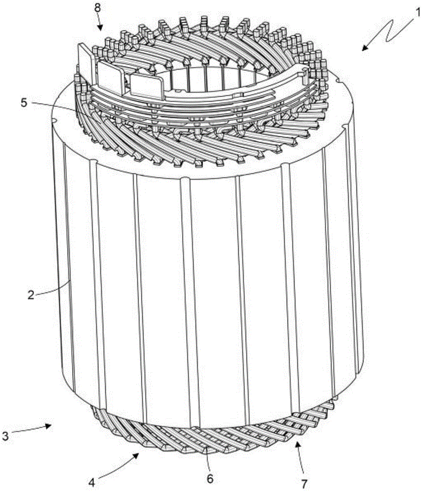
[0028] exist figure 1 In , the reference number 1 represents as a whole the stator of a synchronous motor for reversible automatic traction (that is, it can be operated as a machine by absorbing electrical energy and generating mechanical drive torque, and as an electric motor absorbing mechanical energy and generating electrical energy dynamo). The stator 1 has a cylindrical tubular shape, and is arranged around a rotor (not shown) so as to enclose the rotor itself therein.

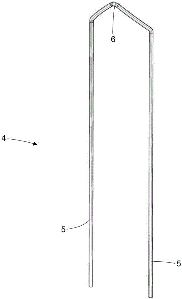
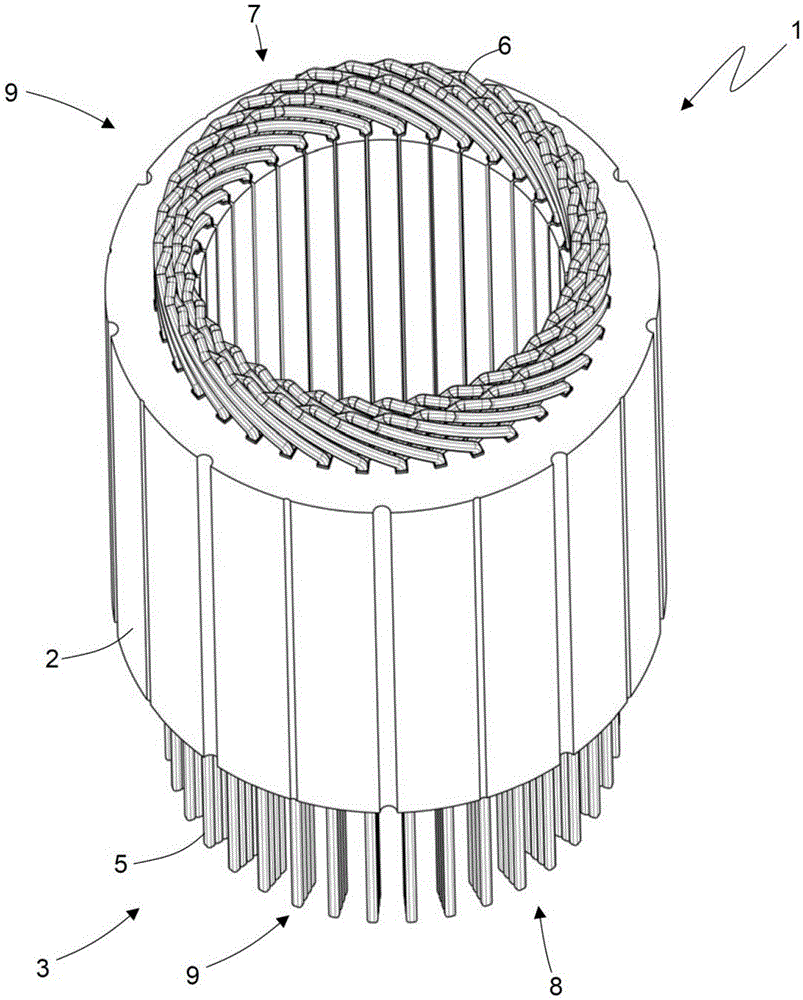
[0029] The stator 1 includes a magnetic core 2, which is composed of a series of sandwich sheets and is tubular with a central hole; the magnetic core 2 is passed longitudinally by thirty-six stator slots evenly distributed along the inner side of the magnetic core 2, and accommodates three Phase stator winding 3 (obviously the number of stator slots can be different). A three-phase stator winding 3 comprises a series of rigid U-shaped bars 4, each bar 4 comprising two legs 5 connected to each other by...


PUM


Abstract

Method and station (9) for the construction of a stator winding (3) with rigid bars (4) for a rotary electrical machine; an insulated wire (12) of electrically conductor material and provided on the outside with an insulating layer (14) is unwound from a coil (11); a final end of the insulated wire (12) is bent in a ''U'' shape so as to create a bar (4) having two legs (5) connected to one another by a cusp (6); the insulated wire (12) is transversely cut to separate the rigid bar (4) from the remaining part of the wire (12); and the bar (4) is inserted into a stator slot of a magnetic core (2) of a stator (1); furthermore, the electrical conductivity is measured between the core (13) and the outer surface of the insulated wire (12) by means of a first electrode (25) electrically and permanently connected to the core (13) of the insulated wire (12) and a second electrode (26), which rubs against the outer surface of the insulated wire (12).

Description

technical field [0001] The invention relates to a method and a construction station for constructing a stator winding with rigid bars in a rotating electric machine. Background technique [0002] Usually, the stator winding of an electric machine is obtained by linear flexible conductors with circular cross-section, which are initially wound into coils, which are then inserted into stator slots and then electrically connected to each other. Said construction method is complex and cannot be automated because it is difficult to automate the insertion of the coils into the stator slots, does not have a stable shape of the coils and has to deform while passing through the small axial openings of the slots. [0003] In order to overcome the constructional difficulty of obtaining a stator winding from a linear flexible conductor with a circular cross section, it has been proposed to obtain the stator winding by a rigid rod with a rectangular cross section. In the stator winding o...

Claims


Application Information

Patent Timeline
Patent Type & Authority Applications(China)
IPC IPC(8): H02K15/04
CPCH02K15/0421H02K11/20Y10T29/53161Y10T29/49073Y10T29/53022Y10T29/49004H02K15/0414H02K15/085
Inventor M·马格里F·钱波利尼
Owner FAB ITAL MAGNETI MARELLI SPA
Features
  • Generate Ideas
  • Intellectual Property
  • Life Sciences
  • Materials
  • Tech Scout
  • Unparalleled Data Quality
  • Higher Quality Content
  • 60% Fewer Hallucinations
Learn More