
A friction stir welding electric spindle device with retraction function

A friction stir welding and electric spindle technology, applied in welding equipment, non-electric welding equipment, metal processing equipment, etc., can solve the problems of poor structure compactness, machine tool failure, affecting the use of welding machine tools, etc., to achieve simple structure and improve reliability. Effect

Active Publication Date: 2019-07-26
SHANGHAI AEROSPACE EQUIP MFG GENERAL FACTORY
View PDF9 Cites 0 Cited by
  • Summary
  • Abstract
  • Description
  • Claims
  • Application Information

AI Technical Summary

Problems solved by technology

The advantage of this structure is that the structure has a large torque and is easy to implement. The disadvantage is that the machine tool has a complex structure, a relatively large volume, poor structural compactness, and high requirements for the installation and debugging of the machine tool.
In addition, due to the existence of the welding angle during the welding process of this structure, especially when the universal joint is not adjusted in place, the universal joint will generate a lot of noise during the welding process, which will cause the machine tool to malfunction in severe cases , affecting the use of welding machine tools

Method used


Image

  • A friction stir welding electric spindle device with retraction function

Examples


Embodiment Construction

[0018] The invention will be described in more detail hereinafter with reference to the accompanying drawings showing embodiments of the invention. However, this invention may be embodied in many different forms and should not be construed as limited to the embodiments set forth herein.

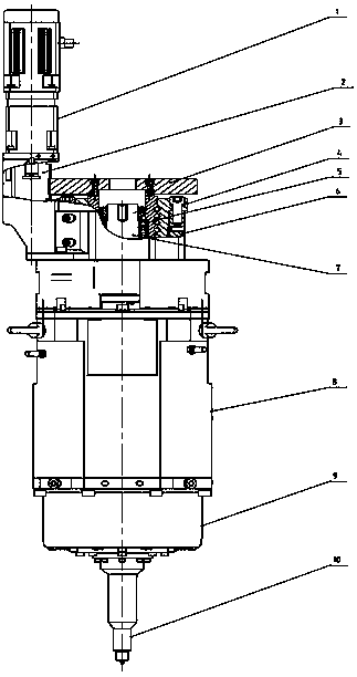
[0019] Such as figure 1 As shown, the friction stir welding electric spindle device with retraction function provided by the preferred embodiment of the present invention includes: retraction drive assembly 1, retraction gear A2, retraction gear B3, lead screw nut 4, ball screw 5, connection Part A6, internal and external spline shaft 7, built-in hollow motor 8, connector B9, stirring head 10.

[0020] The retraction drive assembly 1, the retraction gear A2, the lead screw nut 4 and the connector A6 are connected by screws; the retraction gear B3 is connected to the ball screw 5 by screws, and the ball screw 5 is connected to the internal and external spline shaft 7 through the bearing. The...


PUM


Abstract

The invention discloses a friction stir welding electric spindle device having a retraction function. The device comprises a retraction driving assembly, a retraction gear A, a retraction gear B, screw nuts, a ball screw, a connecting piece A, inner and outer spline shafts, an internal hollow motor, a connecting piece B and a stirring head, wherein the internal hollow motor is matched and connected with the inner spline shaft by the aid of a shaft hole, the outer spline shaft and the inner spline shaft are connected by the aid of splines, and the outer spline shaft is connected with the stirring head; when the internal hollow motor works, the inner spline shaft is driven to drive the outer spline shaft to move by the aid of a spline pair, and a spindle rotates; the retraction driving assembly transmits movement to the screw nuts by the aid of the retraction gear A and the retraction gear B to drive the ball screw to move up and down; the ball screw is connected with the outer spline shaft so as to drive the stirring head connected onto the outer spline shaft to move up and down, the stirring head retracts gradually during work, and keyhole-free friction stir welding is realized.

Description

technical field [0001] The invention relates to the field of friction stir welding, in particular to a friction stir welding electric spindle device with a retraction function. Background technique [0002] Friction stir welding is a high-speed rotating stirring head pierced into the workpiece and then moves along the welding direction. Frictional heat is generated at the contact part between the stirring head and the workpiece, so that the surrounding metal forms a plastic softening layer, and the stirring head shaft shoulder and the stirring pin And the solid phase welding method that realizes material connection under extrusion. During friction stir welding, it is required that the shoulder surface of the welding head has an included angle with the welding plane (that is, the inclination angle of the welding process), so that the shoulder of the stirring head can provide sufficient upsetting pressure. Therefore, the friction stir welding machine tool should also have a d...

Claims


Application Information

Patent Timeline
Patent Type & Authority Patents(China)
IPC IPC(8): B23K20/12
Inventor 林永勇郭立杰张华德
Owner SHANGHAI AEROSPACE EQUIP MFG GENERAL FACTORY
Learn More