Eureka AIR delivers breakthrough ideas for toughest innovation challenges, trusted by R&D personnel around the world.

Plastic plate cutting machine

A plastic sheet and cutting machine technology, applied in metal processing and other directions, can solve the problems of low processing precision, low processing efficiency, and inflexibility, and achieve the effect of strengthening the frame structure, good cutting effect, and ensuring flushness

Inactive Publication Date: 2016-06-01
WUXI FORMEN TECHN
View PDF0 Cites 5 Cited by
  • Summary
  • Abstract
  • Description
  • Claims
  • Application Information

AI Technical Summary

Problems solved by technology

However, the existing technology generally only separates different materials by manual peeling or sawing, which has low processing efficiency and is easy to hurt hands.
Roughly machined or formed plastic products have a certain hardness and cannot be further processed by hand, and can only be trimmed by using a plastic product cutting machine
The saw blade has no protective measures and is exposed to the outside. It is not very safe for the saw blade and the operator. When the plastic is cut by manual operation, the direction of the thrust is not fixed, and the plastic is not pressed tightly, which will easily cause uneven cutting edge and processing. The precision is low, not flexible enough, which also reduces the production efficiency. During the cutting process, plastic debris is easy to splash and pollute the environment.

Method used


Image

  • Plastic plate cutting machine
  • Plastic plate cutting machine
  • Plastic plate cutting machine

Examples


Embodiment Construction

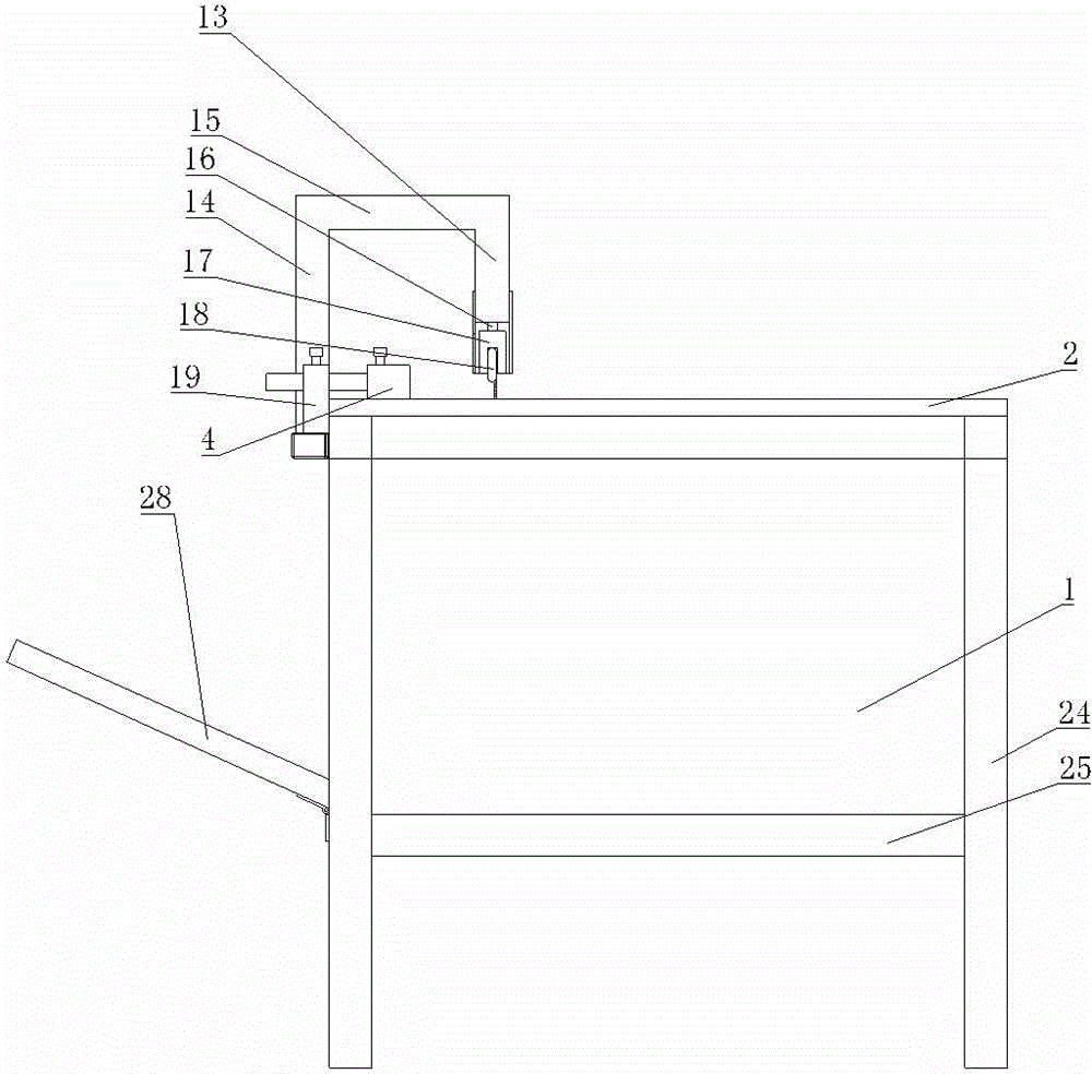
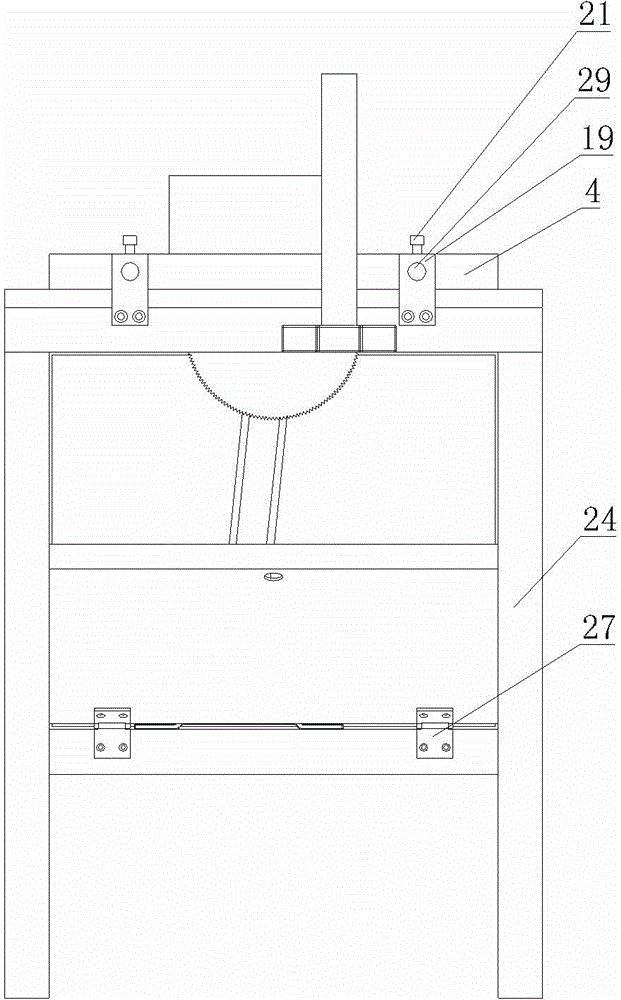
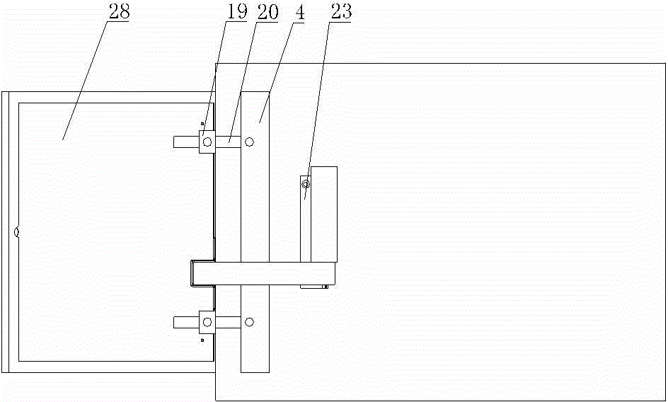
[0019] Such as figure 1 , figure 2 , image 3 , Figure 4 , Figure 5 , Figure 6 , Figure 7 , including a frame 1, the upper end of the frame 1 is fixed with a horizontal top plate 2, the top plate 2 is provided with a saw groove 3 parallel to the cutting direction, and one side of the saw groove 3 is provided with a parallel plate 4 parallel to the saw groove 3 One side of the top plate 2 is also provided with a pressing mechanism, the bottom of the frame 1 is provided with a motor mounting seat 5, and the lower side of the corresponding top plate 2 is fixed with a spindle box 6 by bolts, and a motor 7 is installed on the motor mounting seat 5. The output shaft is connected with a driving pulley 8, the spindle box 6 includes a main shaft, a driven pulley 9 is installed on one end of the main shaft, the driving pulley 8 and the driven pulley 9 are fixedly connected by a belt 10, and the corresponding other end of the main shaft is connected with a saw blade 11, The up...


PUM


Abstract

The invention provides a plastic plate cutting machine which is simple in structure, convenient to operate, capable of conveniently cutting plastic, good in cutting effect, capable of ensuring flush cut edges, high in safety coefficient and capable of protecting operators and a saw blade against injuries and damage. The plastic plate cutting machine comprises a machine frame, a top plate which is horizontally arranged is fixed to the upper end of the machine frame, and a saw groove parallel to the cutting direction is formed in the top plate. The plastic plate cutting machine is characterized in that a parallel plate parallel to the saw groove is arranged at one side of the saw groove, and a pressing mechanism is further arranged on one side of the top plate; a motor mounting seat is arranged on the lower portion of the machine frame, and a spindle box is fixed to the lower side corresponding to the top plate through bolts; a motor is mounted on the motor mounting seat, and an output shaft of the motor is connected with a driving belt pulley; the spindle box comprises a spindle, a driven belt pulley is mounted at one end of the spindle, and the driving belt pulley and the driven belt pulley are fixedly connected through a belt; the saw blade is connected to the other corresponding end of the spindle, and the upper end of the saw blade can stretch out of the saw groove.

Description

technical field [0001] The invention relates to the technical field of cutting equipment, in particular to a plastic plate cutting machine. Background technique [0002] At present, plastic has become one of the most important raw materials today, and various items processed from plastic are full of people's lives. However, in the prior art, different materials are generally only separated by manual peeling or sawing, which has low processing efficiency and is easy to hurt hands. Roughly machined or shaped plastic products have a certain hardness and cannot be further processed by hand, so they can only be trimmed with a plastic product cutting machine. The saw blade has no protective measures and is exposed to the outside. It is not very safe for the saw blade and the operator. When the plastic is cut by manual operation, the direction of the thrust is not fixed, and the plastic is not pressed tightly, which will easily cause uneven cutting edge and processing. The precis...

Claims


Application Information

Patent Timeline
Patent Type & Authority Applications(China)
IPC IPC(8): B26D1/15B26D7/26B26D5/08B26D7/00B26D7/02B26D7/22
Inventor 田芸
Owner WUXI FORMEN TECHN
Why Eureka
Eureka Blog
Learn More