
Clamp-type elevator device for heavy steel plate blank and using method thereof

A steel slab and clamping technology, which is applied in the field of clamping and lifting devices for heavy steel slabs. It can solve the problems of steel slab clamping, fastening, lack of a good technical solution, and the inability of limbs and feet to reach in, etc. problems, to achieve the effect of light weight, small deformation and wide application

Active Publication Date: 2016-06-01
SHANGHAI ERSHIYE CONSTR CO LTD +1
View PDF6 Cites 0 Cited by
  • Summary
  • Abstract
  • Description
  • Claims
  • Application Information

AI Technical Summary

Problems solved by technology

[0004] 1) The size of the clamps for both limbs is huge, and there is not enough space above the steel blanks that are not in the shape of a "well" and are stacked up and down in layers regularly to allow the clamps to go deep, or the hooks of the limbs and feet cannot extend into the underside of the steel blanks
[0005] 2) For the steel blank with a large inclination angle, since the relative positions of the four limbs and feet of the double-leg fixture are fixed, it is impossible to clamp and fasten at the center of gravity of the steel blank
[0006] 3) If the steel blank with a large inclination angle is forcibly hoisted at a non-center of gravity position, due to the heavy weight of the steel blank, the component of its gravity in the tilt direction is much greater than the friction exerted by the four limbs on the steel blank, and sliding blanks are prone to occur ACCIDENT
However, the working method of the improved hoisting tool is still horizontal clamping, and there is still no good technical solution for the hoisting of excessively large inclination angles and irregularly stacked plates

Method used


Image

  • Clamp-type elevator device for heavy steel plate blank and using method thereof
  • Clamp-type elevator device for heavy steel plate blank and using method thereof

Examples


Embodiment Construction

[0031] The present invention is further illustrated below by specific examples.

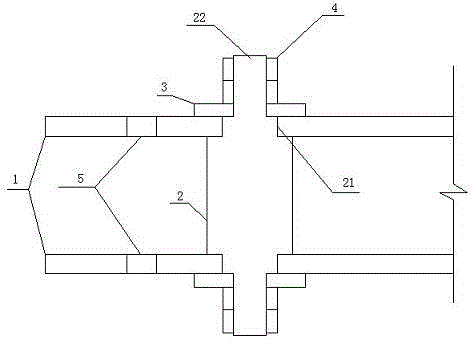
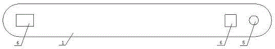
[0032] Such as figure 1 , figure 2 As shown, a clamp-type clamping and lifting device for heavy steel plate blanks, which includes two splints 1, two connecting rods 2, a number of gaskets 3 and lock nuts 4; one end of the splint 1 is provided with a lifting hole 5 and the splint 1 Both ends of the connecting rod are provided with connecting holes 6 for connecting rods to pass through, wherein the connecting holes 6 near the side of the lifting hole 5 are located inside the lifting hole 5; Section 21, the threaded locking section 22 located at both ends of the perforated section 21, the cross-sectional shape of the perforated section 21 is the same as the opening shape of the connecting hole 6, and the two splints 1 pass through the connecting holes 6 and pass through the two connecting rods 2 respectively. On the perforated section 21, the gasket 3 is set on the threaded locking section 22 of...


PUM


Abstract

The invention relates to the field of steel production in the metallurgical industry, in particular to a clamp-type elevator device for a heavy steel plate blank. The clamp-type elevator device for the heavy steel plate blank is characterized in that the device comprises two clamping plates, two connecting rods, a plurality of gaskets and lock nuts; lifting holes are formed in one end of each clamping plate, connecting holes allowing the corresponding connecting rods to penetrate through are formed in the two ends of each clamping plate, and the connecting holes close to the sides of the lifting holes are located in the inner sides of the lifting holes; each connecting rod comprises a connecting section located in the middle, punching sections located at the two ends of the corresponding connecting section, and thread locking sections located at the two ends of the corresponding punching section; the cross-section shape of the punching sections is the same as the opening shape of the connecting holes; the two clamping plates penetrate into the punching sections of the two connecting rods through the corresponding connecting holes, the gaskets are arranged on the thread locking sections of the connecting rods in a sleeving mode, and the lock nuts are fixedly connected with the thread locking sections in a threaded mode. The clamp-type elevator device is low in cost, small in deformation in the using process, safe and guaranteed, capable of adjusting the clamp degree, and wide in application range.

Description

technical field [0001] The invention relates to the field of iron and steel production in the metallurgical industry, in particular to a clamping and lifting device for heavy steel plate blanks and a method for using the same. Background technique [0002] In the process of iron and steel casting production, a large number of heavy-duty steel plate blanks (10m long, 1.5m wide, 0.18m thick, and a single piece weighing more than 14t), due to their large size and heavy weight, need to use special large spreaders or fixtures to lift or transport. In order to ensure that the steel plate blank will not fall off the spreader or clamp during transportation, steel mills generally use double-leg clamps. The fixture is made of special steel, and has four rectangularly distributed limbs with fixed relative positions. The lower part of each limb is in the shape of a hook. When transferring the steel blank, the four limb and foot hooks of the double limb fixture are first clamped under ...

Claims


Application Information

Patent Timeline
IPC IPC(8): B66C1/62B66C1/22
Inventor 赵建立王志新王兴康杨宝良张建华杨茂森
Owner SHANGHAI ERSHIYE CONSTR CO LTD
Features
  • Generate Ideas
  • Intellectual Property
  • Life Sciences
  • Materials
  • Tech Scout
  • Unparalleled Data Quality
  • Higher Quality Content
  • 60% Fewer Hallucinations
Learn More