A self-circulating plasma gasifier

A plasma and gasifier technology, which is applied in the gasification process, gasification device electrodes, and the manufacture of combustible gas, etc., can solve the problems of not meeting the application requirements of chemical raw materials, affecting the quality of synthesis gas, and consuming the heat of the gasifier. , to achieve complete gasification, improved efficiency, high decomposition rate and high efficiency

Active Publication Date: 2018-03-16
JINING XINRUIDA INFORMATION TECH CO LTD
View PDF5 Cites 0 Cited by
  • Summary
  • Abstract
  • Description
  • Claims
  • Application Information

AI Technical Summary

Problems solved by technology

[0002] The gasification agent used in the conventional gasification device is water vapor + air or water vapor + oxygen. When the gasifier is working, the water vapor + air or water vapor + oxygen are directly sent into the gasifier to make the water vapor and Coal undergoes a gas-forming reaction to generate synthesis gas, which is an endothermic reaction that requires the oxidation reaction of air or oxygen and carbon to provide heat for it. The gasification rate of this gasification method is low, and at the same time, a large amount of Carbon dioxide waste gas not only affects the quality of synthesis gas, but also causes a large amount of greenhouse gas emissions in post-production
Due to the low calorific value of domestic waste and the low content of fixed carbon in its chemical composition, if conventional gasification technology is used to gasify domestic waste, the endothermic reaction between water vapor and domestic waste will consume the energy of the gasifier. The gasification furnace needs to add coal fuel and input air or oxygen to support the combustion, so that the exhaust gas content in the synthesis gas is high, and the useful components in the obtained synthesis gas are quite low, almost exhaust gas, which cannot meet the application requirements of chemical raw materials

Method used


Image

  • A self-circulating plasma gasifier
  • A self-circulating plasma gasifier
  • A self-circulating plasma gasifier

Examples


Embodiment 1

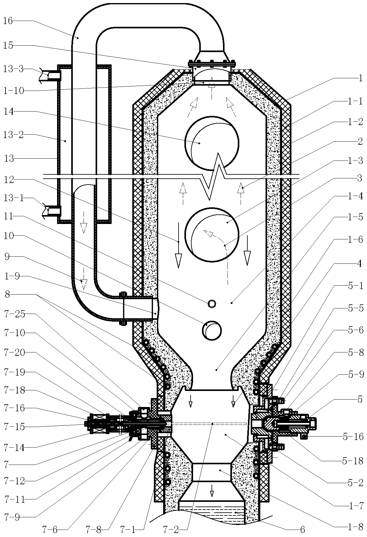
[0021] Example 1 figure 1 In the illustrated embodiment, the self-circulating plasma gasifier includes a plasma device, the gasifier is composed of a refractory furnace wall and an insulating wall, the insulating wall is enclosed on the outer wall of the refractory furnace wall, and the gasifier has a feed inlet The inlet and outlet of syngas are connected, the feed inlet is at the upper part of the gasifier, the outlet of syngas is at the middle of the gasifier, and there is a gasification zone at the lower part of the refractory furnace wall of the gasifier. The top of the furnace 1 is connected to the circulation gas outlet 1-10, and the gasification zone 1-4 at the lower part of the gasification furnace 1 is connected to the circulation gas return port 1-9. 9 is communicated with a circulation return pipe 16, and there is a cooling device 13 on the circulation return pipe 16. The cooling device 13 is a cylindrical structure with both ends closed. The space between the inn...


PUM


Abstract

The invention provides a self-circulation plasma gasification furnace and relates to plasma equipment. The self-circulation plasma gasification furnace comprises a gasification furnace body and a plasma device. The gasification furnace body is formed by a fireproof furnace wall and a heat preservation wall, the gasification furnace body is provided with a feeding port for feeding and a synthesis gas outlet for discharging, a gasification area is arranged on the lower portion in the fireproof furnace wall of the gasification furnace body, a circulation gas outlet for discharging is formed in the top of the gasification furnace body, a circulation return gas port for feeding is formed in the gasification area on the lower portion of the gasification furnace body, the circulation gas outlet and the circulation return gas port are communicated through a circulation return gas pipe, a plasma electric arc area is arranged below the gasification area in the gasification furnace body, and a first discharging assembly and a second discharging assembly of the plasma device are installed on the part, at the plasma electric arc area, of the fireproof furnace wall. The self-circulation plasma gasification furnace is suitable for being applied to the field of solid waste disposal, and solid organic waste is converted into hydrogen-rich synthesis gas meeting the application requirement of chemical materials; water vapor, soot, tar and the like generated in the drying and pyrolyzing process of the raw materials return to the gasification area through the circulation return gas pipe for secondary gasification, and complete gasification is achieved.

Description

technical field [0001] The invention relates to electromechanical equipment, in particular to a gasification equipment. Background technique [0002] The gasification agent used in the conventional gasification device is water vapor + air or water vapor + oxygen. When the gasifier is working, the water vapor + air or water vapor + oxygen are directly sent into the gasifier to make the water vapor and Coal undergoes a gas-forming reaction to generate synthesis gas, which is an endothermic reaction that requires the oxidation reaction of air or oxygen and carbon to provide heat for it. The gasification rate of this gasification method is low, and at the same time, a large amount of Carbon dioxide waste gas not only affects the quality of synthesis gas, but also causes a large amount of greenhouse gas emissions in post-production. Due to the low calorific value of domestic waste and the low content of fixed carbon in its chemical composition, if conventional gasification techn...

Claims


Application Information

Patent Timeline
Patent Type & Authority Patents(China)
IPC IPC(8): C10J3/18C10J3/20C10J3/66
CPCC10J3/18C10J3/20C10J3/66C10J2200/12C10J2300/0916C10J2300/092C10J2300/0946C10J2300/0976C10J2300/1807
Inventor 周开根
Owner JINING XINRUIDA INFORMATION TECH CO LTD
Why Eureka
Try Eureka