
Web forming device for air laid machine

A web-forming machine and web-forming technology, applied in roll-forming mechanism, textile and papermaking, fiber processing, etc., can solve the problems of affecting the working environment, unfavorable health, easy to disperse, etc., to ensure the efficiency of web-forming and avoid secondary pollution , the effect of reducing work intensity

Inactive Publication Date: 2016-06-01
SUZHOU VOCATIONAL UNIV
View PDF6 Cites 2 Cited by
  • Summary
  • Abstract
  • Description
  • Claims
  • Application Information

AI Technical Summary

Problems solved by technology

[0007] Although the web-forming device with the above structure can meet the requirements of web-forming, the following confusion often occurs during actual use: due to electrostatic effects, non-woven fibers tend to be stubbornly attached to the surface of the web-forming curtain 10, so it is necessary to Cleaning by workers during downtime, usually twice per shift (once in the morning and once in the afternoon)
Thus, on the one hand, the extra work intensity of the online workers is increased, and on the other hand, the operating efficiency of the equipment is affected due to the long cleaning time; Corresponding effects (inhalation of fiber dust is not good for health)

Method used


Image

  • Web forming device for air laid machine
  • Web forming device for air laid machine

Examples


Embodiment Construction

[0023] In order to enable the public to understand the technical essence and beneficial effects of the present invention more clearly, the applicant will describe in detail below by way of examples, but the description of the examples is not intended to limit the solution of the present invention, and any concept based on the present invention Equivalent transformations made only in form rather than substantive should be regarded as the scope of the technical solution of the present invention.

[0024] In the following description, all concepts related to the directionality or orientation of up, down, left, right, front and back are for figure 1 In terms of the position and state, it cannot be construed as a special limitation on the technical solution provided by the present invention.

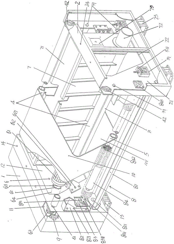
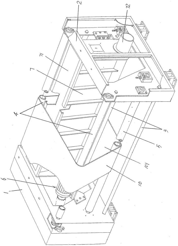
[0025] See figure 1 , showing a first cage 1 formed with a first cage cavity 11, a second cage 2 formed with a second cage cavity 21, and a cage support Tube 3, a pair of upper guide roll...


PUM


Abstract

The invention discloses a web forming device for an air laid machine and belongs to non-woven machinery. The device comprises a first web forming box stand, a second web forming box stand, a set of web forming box stand supporting pipes, a web forming curtain upper guide roller, a web forming curtain lower guide roller, a web forming curtain, a web forming curtain driving device and a web forming curtain induced draft box, wherein the first web forming box stand and the second web forming box stand are oppositely arranged, the set of web forming box stand supporting pipes are fixed between the first web forming box stand and the second web forming box stand, the web forming curtain upper guide roller and the web forming curtain lower guide roller are supported between the first web forming box stand and the second web forming box stand and sleeved with the web forming curtain, the web forming curtain driving device is arranged on the first web forming box stand, the web forming curtain induced draft box is arranged between the first web forming box stand and the second web forming box stand, and an opening of a web forming curtain induced draft box cavity faces upwards and makes contact with the inner side of the web forming curtain. The device is characterized by further comprising an automatic web forming curtain cleaning mechanism, and the automatic web forming curtain cleaning mechanism is arranged between the first web forming box stand and the second web forming box stand corresponding to the position below the front side of the web forming curtain and makes contact with the surface of the side, backing onto a web forming curtain cavity, of the web forming curtain. By the adoption of the device, work strength is reduced, web forming efficiency is guaranteed, and secondary pollution is avoided.

Description

technical field [0001] The invention belongs to the technical field of non-woven machinery, in particular to a web forming device of an air-laid machine. Background technique [0002] The function of the aforementioned airlaid machine is to form a cotton web from the non-woven fibers opened by the previous process, and transport it to the subsequent setting equipment (ie, non-woven product forming equipment such as needle punching machine, spunlace machine and pressing machine. etc.) into non-woven fabrics, thermal insulation materials, sound insulation felts, automotive interior parts, household bedding products such as cushions and seat cushions, etc. [0003] The airlaid machine uses a high-speed rotating carding roller to disperse the non-woven fibers in the airflow field while carding the non-woven fibers, and makes the non-woven fibers in a three-dimensional distribution state, that is, a basically non-directional messy state. Because air-laid has wide adaptability to...

Claims


Application Information

Patent Timeline
Patent Type & Authority Applications(China)
IPC IPC(8): D04H1/732D01G25/00
CPCD01G25/00D04H1/732
Inventor 顾丽亚丁燕田春娥郑爱权王成田川朱学超张义平
Owner SUZHOU VOCATIONAL UNIV
Learn More