Hydraulic control loop for retractable ironing vibration motors and roadbed slope vibrating motors

A vibration motor and control circuit technology, applied in servo motors, roads, roads, etc., can solve problems such as inconvenient installation and complicated pipelines, and achieve the effect of improving flatness, low cost and good use effect

Inactive Publication Date: 2016-06-01
SHAANXI JOINTARK MASCH GRP CO LTD
View PDF7 Cites 0 Cited by
  • Summary
  • Abstract
  • Description
  • Claims
  • Application Information

AI Technical Summary

Problems solved by technology

However, the fully hydraulic paver telescopic screed vibration circuit and slope vibration circuit currently on the market have complicated pipelines and inconvenient installation, which cannot meet the requirements.

Method used


Image

  • Hydraulic control loop for retractable ironing vibration motors and roadbed slope vibrating motors

Examples


Embodiment Construction

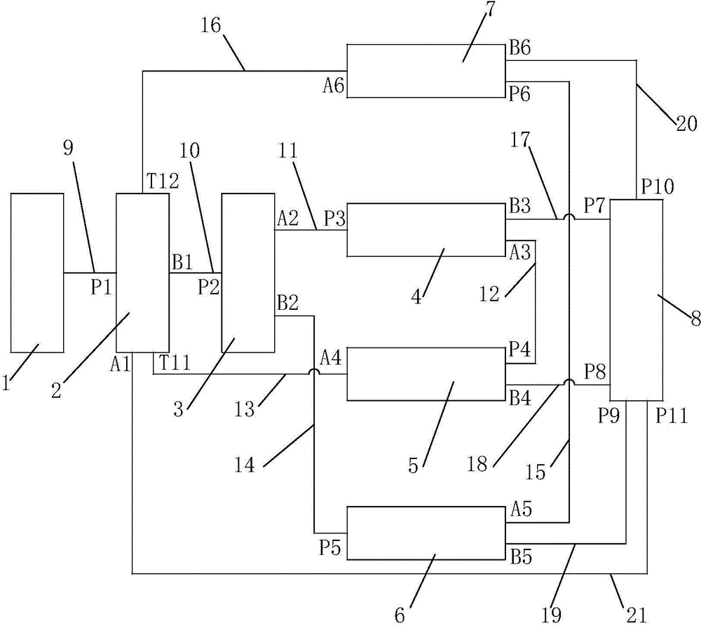
[0023] like figure 1 The hydraulic control circuit of a telescopic screed vibrating motor and roadbed slope vibrating motor shown includes an oil absorbing body 1, a hydraulic pump 2, a diverter valve 3, a left slope vibrating motor 4, a right slope vibrating motor 5, a left telescopic vibrating Tamping motor 6, right telescopic vibrating motor 7, oil return body 8, first pipeline 9, second pipeline 10, third pipeline 11, fourth pipeline 12, fifth pipeline 13, sixth pipeline 14. The seventh pipeline 15, the eighth pipeline 16, the ninth pipeline 17, the tenth pipeline 18, the eleventh pipeline 19, the twelfth pipeline 20 and the thirteenth pipeline 21; the oil suction The body 1 is connected to the oil inlet P1 of the hydraulic pump 2 through the first pipeline 9, and the working oil port B1 of the hydraulic pump 2 is connected to the oil inlet P2 of the diverter valve 3 through the second pipeline 10, and the diverter valve The working oil port A2 of 3 is connected to the oi...


PUM


Abstract

The invention discloses a hydraulic control loop for retractable ironing vibration motors and roadbed slope vibrating motors. The hydraulic control loop comprises an oil absorption body, a hydraulic pump, a flow dividing valve, the left slope vibrating motor, the right slope vibrating motor, the right retractable vibration motor and the left retractable vibration motor. The oil absorption body is connected with an oil inlet P1 of the hydraulic pump. A working oil port B1 of the hydraulic pump is connected with an oil inlet P2 of the flow dividing valve. A working oil port A2 of the flow dividing valve is connected with an oil inlet P3 of the left slope vibrating motor. An oil outlet A3 of the left slope vibrating motor is connected with an oil inlet P4 of the right slope vibrating motor. An oil outlet A4 of the right slope vibrating motor is connected with an oil return port T11 of the hydraulic pump. A working oil port B2 of the flow dividing valve is connected with an oil inlet P5 of the left retractable vibration motor. An oil outlet A5 of the left retractable vibration motor is connected with an oil inlet P6 of the right retractable vibration motor. An oil outlet A6 of the right retractable vibration motor is connected with an oil return port T12 of the hydraulic pump. By means of the hydraulic control loop for the retractable ironing vibration motors and the roadbed slope vibrating motors, consistent vibrating frequency of the left and right slope vibrating motors and consistent vibration frequency of left retractable ironing and right retractable ironing can be achieved.

Description

technical field [0001] The invention belongs to the technical field of paver hydraulic systems, and in particular relates to a hydraulic control circuit of a telescopic screed vibrating motor and a roadbed slope vibrating motor. Background technique [0002] The paver is a construction equipment mainly used for paving various materials on the base and surface of the road. During use, when the width of the road surface changes and the side slope of the roadbed exists at the same time, it is necessary to use the telescopic motor and the side slope motor at the same time. However, the full-hydraulic paver telescopic screed vibration and side slope vibration circuits currently on the market have complicated pipelines and inconvenient installation, which cannot meet the requirements. Contents of the invention [0003] The object of the present invention is to overcome the above-mentioned deficiencies in the prior art, and provide a hydraulic control circuit for a telescopic sc...

Claims


Application Information

Patent Timeline
Patent Type & Authority Applications(China)
IPC IPC(8): E01C19/12F15B11/16
Inventor 綦开隆孙雪妮
Owner SHAANXI JOINTARK MASCH GRP CO LTD
Why Eureka
Try Eureka