Rotary engine with variable speed driven piston

A rotary engine and engine technology, applied to rotary piston engines, rotary or swinging piston engines, internal combustion piston engines, etc., can solve the problems of large area, low thermal efficiency, large heat loss, etc., and achieve high thermal efficiency and low frictional resistance , The effect of high torque output efficiency

Active Publication Date: 2022-02-01
李国令
View PDF5 Cites 0 Cited by
  • Summary
  • Abstract
  • Description
  • Claims
  • Application Information

AI Technical Summary

Problems solved by technology

One of its fatal flaws is that its combustion chamber is a long and narrow shape, so the area is too large and the heat loss is also large.
Therefore, the thermal efficiency is lower than that of reciprocating engines

Method used


Image

  • Rotary engine with variable speed driven piston
  • Rotary engine with variable speed driven piston
  • Rotary engine with variable speed driven piston

Examples


Embodiment Construction

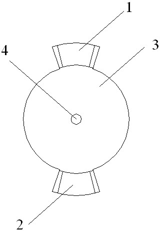
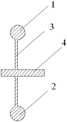
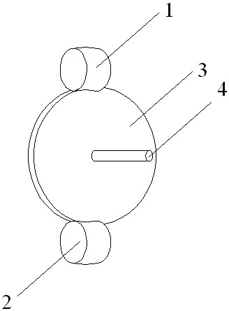
[0062] Figure 1 to Figure 19 A first implementation example is shown.

[0063] The rotary engine of this implementation case has two power pistons, figure 1 It is the front view of the power piston and power disc, figure 2 is a sectional view, image 3 It is a three-dimensional schematic diagram of the power piston and the power disc. The first power piston 1 and the second power piston 2 are fixed on the periphery of the power disc 3. The two power pistons 1 and 2 are separated by about 180 degrees. The center of the power disc 3 has PTO shaft 4, Figure 4 It is the front view of the first driven piston 5, the second driven piston 6 and the driven disc 7, Figure 5 is a sectional view, Image 6 It is a three-dimensional diagram. The first driven piston 5 and the second driven piston 6 are fixed on the periphery of the driven disc 7, and the two driven pistons 5 and 6 are separated by about 180 degrees. There is a shaft sleeve 8 in the center of the driven disc 7, and ...


PUM


Abstract

The invention relates to a rotary engine with a variable-speed driven piston, which belongs to the rotary engine. It discloses that the cylinder of the engine is circular, the cylinder section is circular or oval, and there are at least one pair of pistons in each circular cylinder: a power piston and a driven piston, and the power piston is fixed on the power circle. Around the disk, there is a power output shaft in the center of the power disk. The axis of the power output shaft coincides with the central axis of the circular cylinder. The power piston rotates along the circular cylinder at a constant or approximately uniform speed. The circular cylinder moves, and in each circular stroke, the driven piston accelerates to a faster speed than the power piston for a period of time, decelerates to a slower speed than the power piston for another period of time, and stops. The invention has the advantages of high torque output efficiency, large working range and high thermal efficiency of the engine.

Description

technical field [0001] The present invention relates to a rotary engine, in particular, the invention is a rotary engine having a variable speed driven piston. Background technique [0002] Most of the engines we use are reciprocating engines. The piston moves up and down in a straight line in the cylinder. When the piston moves down, air and fuel are sucked into the cylinder; Ignition causes the fuel and air in the cylinder to combust. After the air is heated, it expands and does work, pushing the piston down and driving the crankshaft to rotate through the connecting rod. A rotating crankshaft propels the car forward. The conversion from linear motion to rotary motion produces a large amount of frictional resistance, so the efficiency of the engine is low, the torque is small, and the noise and vibration are large. [0003] There is a technically mature rotary engine on the market called the Wankle engine. It has a triangular rotor piston rotating in an 8-shaped cylind...

Claims


Application Information

Patent Timeline
Patent Type & Authority Patents(China)
IPC IPC(8): F02B53/00F02B55/02
CPCF02B53/00F02B55/02F02B2053/005F01C1/063F02B53/02F02B55/08F02B2730/03F01C1/077Y02T10/12F02B2730/018
Inventor 李巩令
Owner 李国令
Why Eureka
Try Eureka