Concrete pumping equipment hydraulic system and concrete pumping equipment

A technology of concrete pump and hydraulic system, applied in mechanical equipment, fluid pressure actuating device, servo motor, etc., can solve the problems of reversing impact of concrete pumping equipment

Active Publication Date: 2017-09-26
ZOOMLION HEAVY IND CO LTD
View PDF7 Cites 0 Cited by
  • Summary
  • Abstract
  • Description
  • Claims
  • Application Information

AI Technical Summary

Problems solved by technology

[0018] The invention provides a hydraulic system for concrete pumping equipment, which is used to solve the problem of reversing impact of concrete pumping equipment in the prior art

Method used


Image

  • Concrete pumping equipment hydraulic system and concrete pumping equipment
  • Concrete pumping equipment hydraulic system and concrete pumping equipment
  • Concrete pumping equipment hydraulic system and concrete pumping equipment

Examples


Embodiment 1

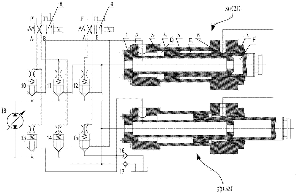
[0067] Such as image 3 with Figure 4 As shown, the two pumping cylinders 30 are respectively the first pumping cylinder 31 and the second pumping cylinder 32, and the number of reversing valves is two, which are respectively the first reversing valve 8 and the second reversing valve 9 , the number of cartridge valves is six, which are the first cartridge valve 10, the second cartridge valve 11, the third cartridge valve 13, the fourth cartridge valve 14, the fifth cartridge valve 15 and the sixth cartridge valve Install the valve 12, wherein, when the hydraulic system adopts the closed rotary pump 18 as the high-pressure oil source, the first main oil circuit and the second main oil circuit are respectively connected to the two oil ports of the closed rotary pump 18, When the hydraulic system uses an open pump as the high-pressure oil source, one of the first main oil circuit and the second main oil circuit that needs to be connected to the high-pressure oil source is conne...

Embodiment 2

[0086] Such as Figure 5 As shown, in addition to the structure in the above-mentioned embodiment 1, this embodiment also includes the seventh cartridge valve 19, the eighth cartridge valve 20 and the ninth cartridge valve 21, and the second cavity E of the first pumping cylinder 31 The seventh cartridge valve 19 is connected to the second cavity E of the second pumping cylinder 32, and the second cavity E of the first pumping cylinder 31 is connected to the first main oil circuit through the eighth cartridge valve 20. The second cavity E of the second pumping cylinder 32 is connected to the second main oil circuit through the ninth cartridge valve 21;

[0087] It also includes a third reversing valve 22, the third reversing valve 22 has a first working position and a second working position, the pilot control chamber of the seventh cartridge valve 19 is connected to the first oil port of the third reversing valve 22, Both the pilot control chamber of the eighth cartridge val...

Embodiment 3

[0092] Such as Image 6 As shown, in this embodiment, different from Embodiment 2, an open pump 24 is used in this embodiment to provide a high-pressure oil source for the hydraulic system, and a fourth reversing valve 23 is also included in this embodiment. The first oil port of the valve 23 is connected to the open pump 24, the second oil port is connected to the oil tank, the third oil port is connected to the first cartridge valve 10, the second cartridge valve 11 and the eighth cartridge valve 20, The fourth oil port is connected with the third cartridge valve 13 , the fourth cartridge valve 14 and the ninth cartridge valve 21 .

[0093] More preferably, the fourth reversing valve 23 is a three-position four-way reversing valve. When the fourth reversing valve 23 is in the first working position, the open pump 24 and the third cartridge valve 13 and the fourth cartridge valve 14 and the ninth cartridge valve 21 are connected, and the oil tank is connected with the first ...


PUM


Abstract

The invention provides a concrete pumping equipment hydraulic system and concrete pumping equipment. The hydraulic system includes: an oil pump and two pumping oil cylinders with three cavities; the first cavity and the third cavity of the two pumping oil cylinders Each cavity is connected to the oil pump through an oil circuit with a cartridge valve; the third cavity of the two pumping cylinders and the oil tank are connected through a three-way oil circuit, and a check valve is set on the branch oil circuit connected to the oil tank , the first cavity of the pumping cylinder also adopts the same connection method as above; the second cavity of the two pumping cylinders communicates with each other, or communicates with the oil pump; The combination of oil cylinder, cartridge valve and reversing valve realizes the control of the high and low pressure pumping of the pumping cylinder. When oil leakage occurs in the installed valve, it will affect the stroke of the pumping cylinder, which improves the stability of the system.

Description

technical field [0001] The invention relates to the technical field of engineering vehicles, in particular to a concrete pumping equipment hydraulic system and concrete pumping equipment. Background technique [0002] In modern engineering construction, a large amount of concrete needs to be transported, and pumping equipment such as towed concrete pumps, vehicle-mounted concrete pumps, and concrete pump trucks are generally used for transportation. [0003] In construction, the construction conditions are often very complicated. When conveying different distances or different grades of concrete, the required concrete pumping pressure varies greatly. At the same time, the requirements for pumping volume are also different under different working conditions. This requires pumping equipment to be able to adapt to a wide range of output pressure ranges and a wide range of pumping quantities. Limited by power, it is generally realized by high-voltage and low-voltage conversion....

Claims


Application Information

Patent Timeline
Patent Type & Authority Patents(China)
IPC IPC(8): F15B11/16F15B13/06E04G21/04
Inventor 李沛林吴斌兴郭岗吴德志高荣芝
Owner ZOOMLION HEAVY IND CO LTD
Why Eureka
Try Eureka