Sliding-flap free-float type

A technology of traps and float balls, applied in steam traps, mechanical equipment, etc., can solve the problems of steam leakage, large starting force, waste of energy, etc.

Inactive Publication Date: 2016-06-01
江苏江恒阀业有限公司
View PDF0 Cites 3 Cited by
  • Summary
  • Abstract
  • Description
  • Claims
  • Application Information

AI Technical Summary

Problems solved by technology

[0004] In order to overcome the shortcomings of the existing lever float type steam traps, which require large starting force, large valve volume, and waste of energy due to steam leakage, the present invention provides a sliding flap floating ball steam trap, which can reduce the starting force and reduce the volume of the valve. At the same time eliminate eddy current, avoid steam leakage and save energy

Method used


Image

  • Sliding-flap free-float type
  • Sliding-flap free-float type
  • Sliding-flap free-float type

Examples


Embodiment Construction

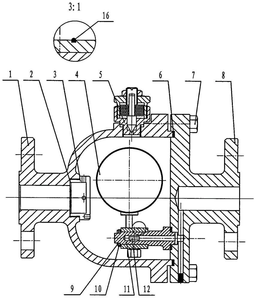
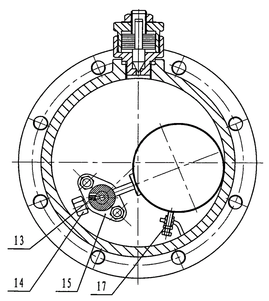
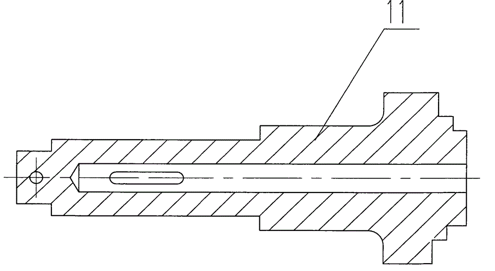
[0012] As shown in the figure, the left valve body 1 and the right valve body 8 are connected by bolts 7 to form a casing, the left valve body 1, the filter screen 2 and the plug 3 are connected in sequence, and the top of the left valve body 1 is equipped with an automatic emptying valve 5 to limit The positioning device 17 is fixed in the left valve body cavity, the floating ball 4, the shaft sleeve 12, and the counterweight 14 are solidified together and set on the valve shaft 11, the counterweight 14 is adjustable, the cotter pin 9, the flat washer 10, the valve The shaft 11, the gland 15, and the right valve body 8 are connected in sequence, and the side of the bushing 12 is processed into a "convex"-shaped hole, the upper part of the "convex" shape is a waist-shaped hole, and the lower part is a rectangular hole, between the valve disc 13 and the rectangular hole For clearance fit, two ring springs 16 are used to press the valve disc 13 on the outer circumference of the s...


PUM


Abstract

Provided is a sliding-flap free-float type. A left valve body and a right valve body are connected via a bolt. The left valve body, a filter screen and a choke plug are connected sequentially. The top of the left valve body is installed with an automatic emptying valve. A limiting device is fixed into a cavity of the left valve body. A floating ball, a shaft sleeve and a weighting block are fixedly connected and sleeve a valve shaft. The weighting block can be adjusted. A cotter pin, a plain washer, the valve shaft, a gland and the right valve body are sequentially connected. The side surface of the shaft sleeve is provided with a convex hole. The upper part is a waist-shaped hole and the lower part is a rectangular hole. A valve clack and a lower-part hole are in clearance fit. Two circular springs are utilized to press the valve clack on the external circumference of the shaft sleeve such that the valve clack and the valve shaft are closely attached. A shaft axis at the right end of the valve shaft is a blind hole. The side surface is provided with a waist-shaped hole. The axial shape and the size are the same as the upper part of the convex-shaped hole of the shaft sleeve. The shaft axis at the right end of the right valve body is provided with a blind hole. The connection between a left end surface and a central hole of the valve shaft is provided with an axial blind hole. The left end is covered by a radial through hole to the center. The outer side end is plugged and communicated with the axial blind hole and the central hole so that a Z-shaped conjugated passage is formed. In combination of condensation water buoyancy and the weighting block, the floating ball ascends or descends to rotate the shaft sleeve and control the passage to open and close. When condensation water flows out of the waist-shaped hole, no eddy occurs. Steam does not leak and energy is saved.

Description

technical field [0001] The invention relates to a sliding flap float trap which can automatically remove condensed water and prevent steam leakage. Background technique [0002] The steam water delivery valve is a valve used to automatically discharge condensed water and prevent steam leakage in various process steam equipment, heat exchangers, steam pipelines and heating lines. Float trap is a mechanical trap, which is a kind of trap that controls the rise and fall of the float by the change of the condensed water level in the valve body, thereby driving the action of the disc. [0003] The basic form of the existing ball float trap is that one end of the lever is connected with a floating ball, the valve disc is in the middle of the lever, and the other end of the lever is hinged with the support. The flap is closed to prevent the steam from flowing out of the valve. Generally, this kind of trap is called a lever float trap, but the trap with this structure has the follow...

Claims


Application Information

Patent Timeline
Patent Type & Authority Applications(China)
IPC IPC(8): F16T1/22
Inventor 刘红施文兵
Owner 江苏江恒阀业有限公司
Why Eureka
Try Eureka