Eureka AIR delivers breakthrough ideas for toughest innovation challenges, trusted by R&D personnel around the world.

Efficient flame burner

A flame nozzle and high-efficiency technology, applied in the directions of burners, combustion methods, combustion types, etc., can solve the problems of insufficient flame length and insufficient combustion of combustible gas, improve combustion effect, reduce flame off-fire phenomenon, and increase flame length. Effect

Inactive Publication Date: 2016-06-01
SHANDONG IRON & STEEL CO LTD
View PDF6 Cites 1 Cited by
  • Summary
  • Abstract
  • Description
  • Claims
  • Application Information

AI Technical Summary

Problems solved by technology

[0004] The purpose of the present invention is to provide a high-efficiency flame burner to solve the technical problems of insufficient combustion of combustible gas injected by the burner and insufficient flame length

Method used


Image

  • Efficient flame burner
  • Efficient flame burner
  • Efficient flame burner

Examples


Embodiment Construction

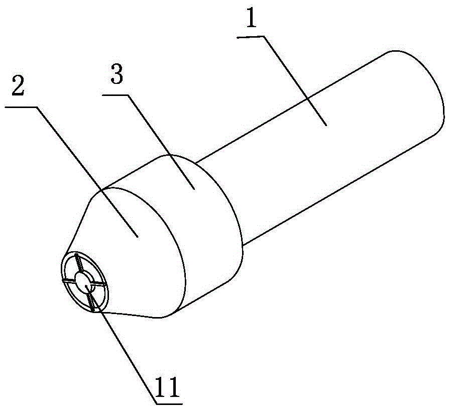
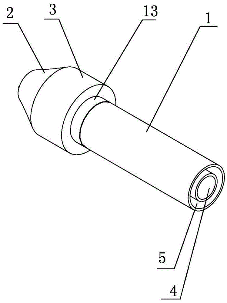
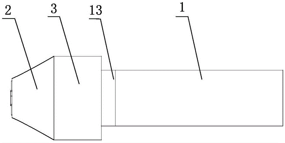
[0027] Such as figure 1 As shown, a high-efficiency flame nozzle includes a sleeve 1, a gas mixing mechanism and an injection pipe 2; the sleeve 1 includes a gas pipe 4 and a combustion-supporting pipe 5, and the combustion-supporting pipe 5 is set on the gas pipe 4 The outside of the gas tube 4 is used to connect combustible gas, and the combustion tube 5 is used to connect oxygen or air; the end of the gas tube 4 is longer than the end of the combustion tube 5, and the gas tube The end of 4 is provided with volatilization tube 6, and described volatilization tube 6 is cylindrical hollow structure, communicates with gas pipe 4, is evenly provided with through hole 7 around volatilization tube 6, and the end of described volatilization tube 6 is provided with end cap, The combustible gas volatilizes to the surrounding side through the through hole 7 of the volatilization tube 6 . Because the end of the gas pipe 4 is longer than the end of the combustion-supporting pipe 5, whe...


PUM


Abstract

The invention relates to an efficient flame burner. The problems that combustible gas jetted by a burner is insufficient in combusting, and the length of flames is not enough are solved. The efficient flame burner comprises a sleeve, a gas mixing mechanism and a jetting pipe; the sleeve comprises a gas pipe and a combustion-supporting pipe, the tail end of the gas pipe is communicated with a volatilization pipe, and through holes are evenly formed in the periphery of the volatilization pipe; and the gas mixing mechanism comprises a fairing and a rotating wheel, wherein the fairing comprises a rear fairing body and a front fairing body. The rear fairing body is fixedly welded to the tail end of the combustion-supporting pipe through a connecting pipe; and the rotating wheel comprises a supporting frame and blades, the jetting pipe is of a conical hollow structure, and a flow guide piece is arranged at the front end of the jetting pipe. The problem that insufficient mixing is caused by parallel blowing of two strands of air flows of combustion-supporting gas and combustible gas is solved, and the combustible gas can be sufficiently combusted.

Description

technical field [0001] The invention relates to the technical field of burners, in particular to a high-efficiency flame burner. Background technique [0002] The steel ladle is used to receive molten steel in the steelmaking plant. When high-temperature molten steel is poured into the ladle, the initial temperature of the ladle is required to be not lower than 800 degrees, otherwise the quality of the molten steel cannot be guaranteed, and the service life of the refractory materials in the ladle will be affected. If the ladle is rebuilt with refractory materials or the ladle is out of service for a long time, the ladle needs to be baked and heated before use. At present, most of them use a roaster to preheat the ladle to ensure the initial temperature. The temperature and length of the flame ejected from the burner of the roaster have a great influence on the roasting effect. [0003] However, the gas ejected from the burner often has the defects of insufficient combustio...

Claims


Application Information

Patent Timeline
Patent Type & Authority Applications(China)
IPC IPC(8): F23D14/02F23D14/62
CPCF23D14/02F23D14/62F23D2203/007F23D2900/14021F23D2900/14701
Inventor 李作鑫曹先锋魏福强李长新白广旻赵珉
Owner SHANDONG IRON & STEEL CO LTD
Why Eureka
Eureka Blog
Learn More