Detector fault diagnosis method and device

A detector and faulty technology, which is applied in the field of detectors, can solve the problems such as the difficulty of locating the fault source in the scanning control system, and achieve the effects of fast and accurate positioning, improving efficiency and reducing burden

Active Publication Date: 2016-06-01
SHANGHAI UNITED IMAGING HEALTHCARE
View PDF9 Cites 3 Cited by
  • Summary
  • Abstract
  • Description
  • Claims
  • Application Information

AI Technical Summary

Problems solved by technology

However, due to the large number of detector units, once a problem occurs during system scanning,

Method used


Image

  • Detector fault diagnosis method and device
  • Detector fault diagnosis method and device

Examples


Example Embodiment

[0012] In order to make the above objectives, features and advantages of the present invention more obvious and understandable, the specific embodiments of the present invention will be described in detail below with reference to the accompanying drawings.

[0013] In the following description, many specific details are set forth in order to fully understand the present invention, but the present invention can also be implemented in other ways different from those described herein, so the present invention is not limited by the specific embodiments disclosed below.

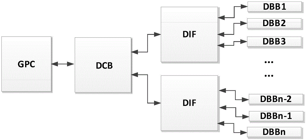
[0014] The present invention provides a fast fault diagnosis process, divides the system into a DCB-DIF link layer and a DIF-DBB link layer, performs fault detection on these two link layers, and improves the speed and accuracy of fault diagnosis .

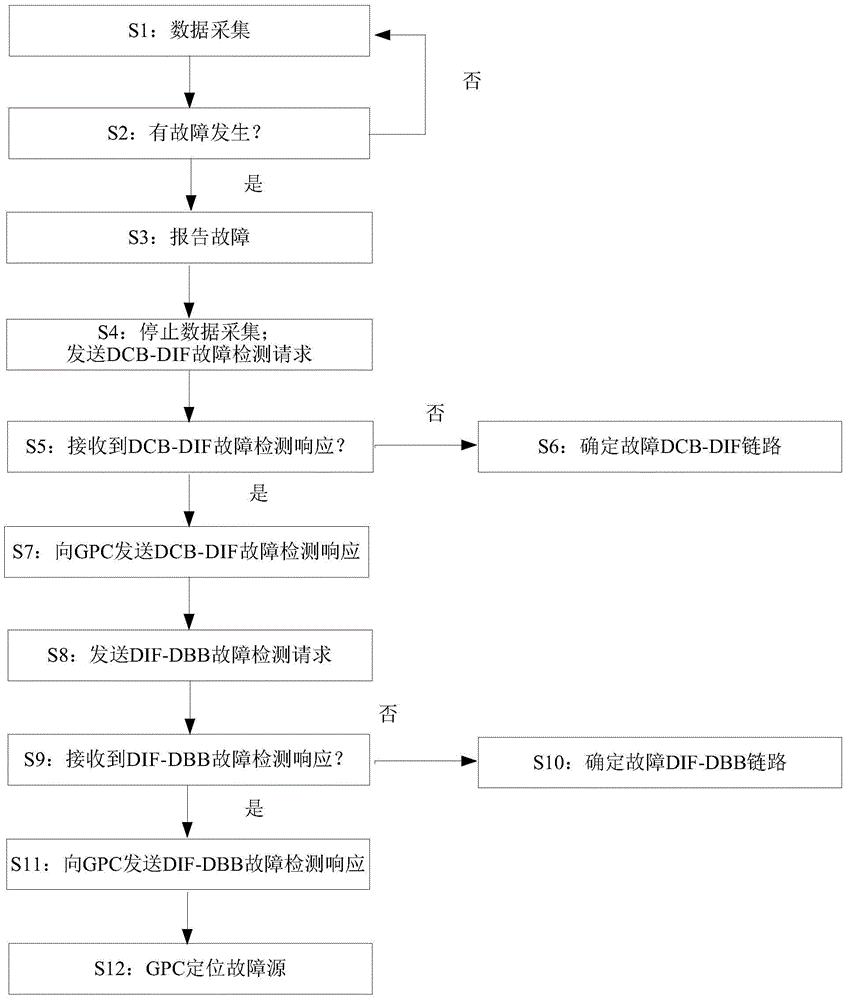
[0015] Such as figure 2 As shown, the detector fault detection method of the present invention includes the following steps:

[0016] Step S1: The DCB sends data collection...


PUM


Abstract

The present invention provides a method and device for carrying out rapid fault diagnosis of a detector. The method comprises the steps that: a data control board sends a data collection command to an associated data interface and the detector in real time when a system is running; the data from the data interface and the detector are processed to determine the existence of a fault; if the fault is determined, the data control board carries out response information collection; and response information is sent to a master control unit, and the master control unit carries out fault positioning.

Description

technical field [0001] The invention mainly relates to a detector in a CT system, in particular to a fast fault diagnosis method and device for the detector. Background technique [0002] CT (computedtomography, computerized tomography) equipment is a fully functional disease detection instrument. X-ray CT equipment mainly includes the following components: X-ray tube, X-ray detector, scanning control system, image acquisition and processing system. In medical applications, by scanning a layer of a certain thickness of the human body, the detector receives the X-rays passing through the layer and converts them into energy intensity signals, and the data acquisition and processing system collects the energy intensity signals and combines them with A certain algorithm reconstructs the original image. Using CT equipment, doctors can clearly observe the conditions of body tissues that are difficult to show on ordinary X-ray films, such as cerebral hemorrhage and various small ...

Claims


Application Information

Patent Timeline
IPC IPC(8): G01T7/00
CPCG01T7/005
Inventor 孔德新
Owner SHANGHAI UNITED IMAGING HEALTHCARE
Why Eureka
Try Eureka