

Orthogonality determination method for direct writing system motion platform
A motion platform and measurement method technology, applied to measurement devices, instruments, optical devices, etc., can solve the problems of long tool cycle, high cost, and difficulty in obtaining testing equipment or testing tools, achieving low cost and fast cycle time. Effect
- Summary
- Abstract
- Description
- Claims
- Application Information
AI Technical Summary
Problems solved by technology
Method used
Image

Examples
Embodiment Construction
[0027] Preferred embodiments of the present invention will be described in detail below in conjunction with the accompanying drawings.
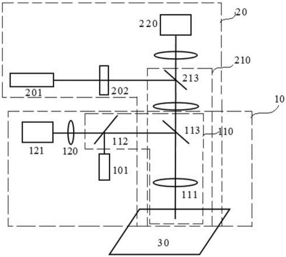
[0028] In order to achieve the purpose of the present invention, as Figure 1 to Figure 4 As shown, in one of the embodiments of the present invention, a method for measuring the orthogonality of the motion platform of the direct writing system is provided, which is characterized in that it includes the following steps:
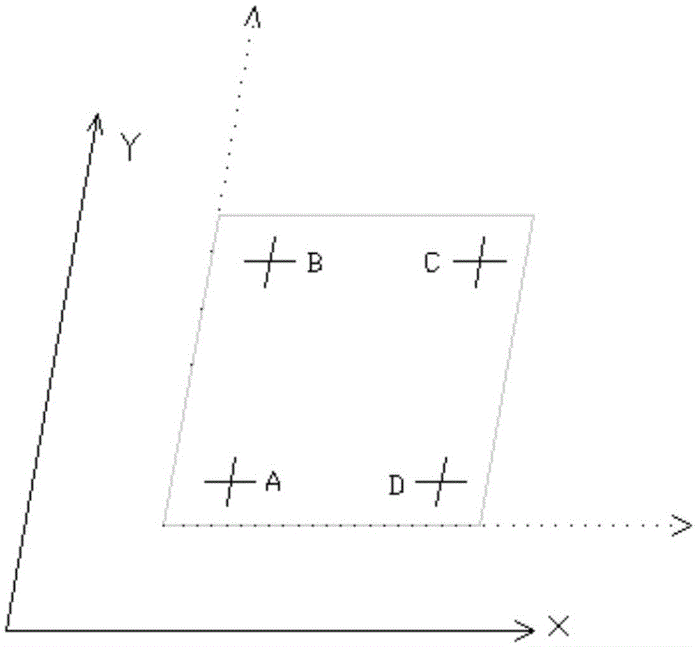
[0029] Step 1, designing a lithography file so that the lithography file has positioning mark points A, B, C, D at the four corners of its surface;
[0030] Step 2, fixing a blank substrate on the motion platform of the direct writing system;
[0031] Step 3, according to the lithography file of step 1, perform direct write exposure on the blank substrate;
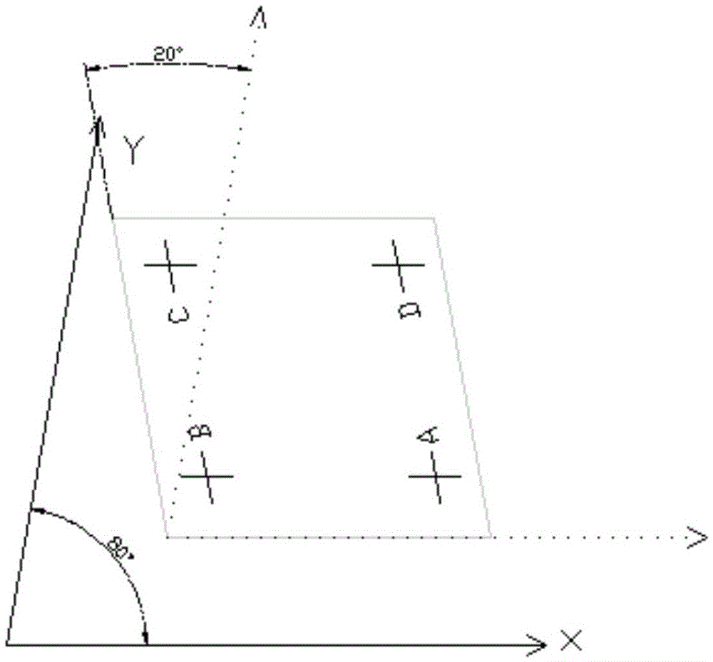
[0032] Step 4, record the XY direction of the motion platform corresponding to each side of the exposed substrate, and then remove the exposed substrate for developmen...
PUM
 Abstract
Description
Claims
Application Information