Energy-saving control circuit for generating multiple magnetic fields

An energy-saving control and magnetic field technology, which is applied in the direction of electric pulse generator circuits, energy storage components to generate pulses, electrical components, etc., can solve the problems of coil heating and single function of magnetic field

Active Publication Date: 2016-06-01
TIANJIN POLYTECHNIC UNIV
View PDF5 Cites 5 Cited by
  • Summary
  • Abstract
  • Description
  • Claims
  • Application Information

AI Technical Summary

Problems solved by technology

[0005] In order to overcome the deficiencies of the above-mentioned prior art, the present invention provides an energy-saving control circuit for generating various magnetic fields, which is based on "Energy-saving control circuit for magnetic field generation based on switch sequenc

Method used


Image

  • Energy-saving control circuit for generating multiple magnetic fields
  • Energy-saving control circuit for generating multiple magnetic fields
  • Energy-saving control circuit for generating multiple magnetic fields

Examples


Embodiment 1

[0035] Embodiment 1, an example of generating a bipolar pulsed magnetic field and saving energy.

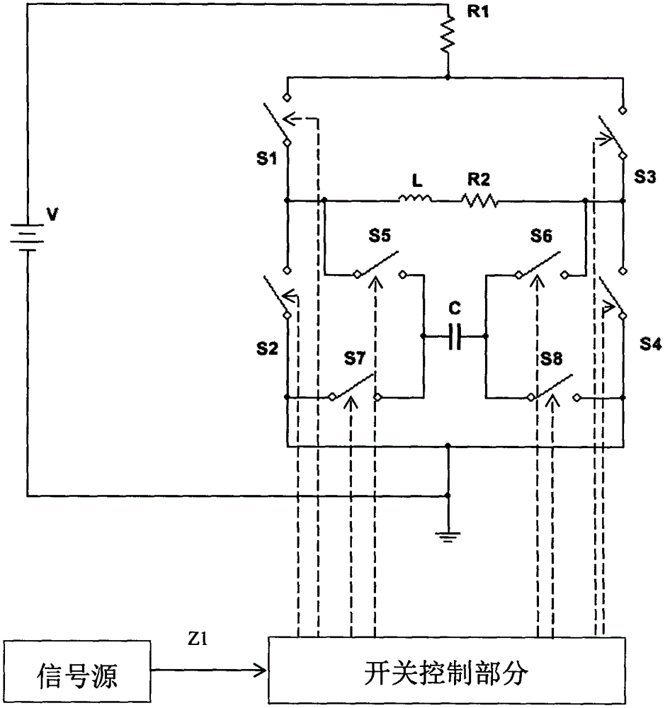
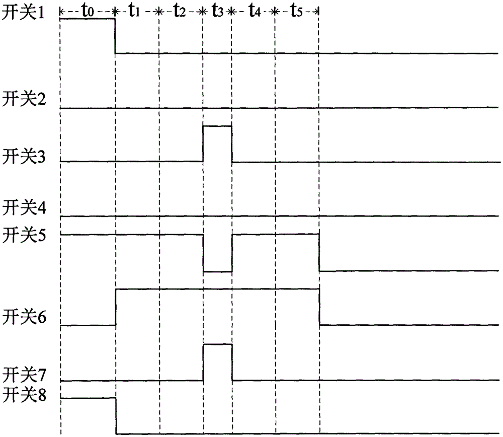
[0036] according to figure 1 and figure 2 As shown, after adjusting the resistance of the adjustable resistor R2, the H-bridge circuit is energized, S1, S5, and S8 in the switch module are controlled by the control signal to close, S2, S3, S4, S6, and S7 are disconnected, and the DC power supply V passes through the resistor R1 Charge the capacitor C for a charging time of t 0 , where t 0 should satisfy t 0 >4.6τ 1 (τ 1 is the RC circuit time constant, τ 1 = R 1 C, R 1 is the resistance value of the adjustable resistor R2, and C is the capacitance value of the capacitor C), because when the charging time of the capacitor is greater than 4.6τ 1 , the voltage across the capacitor reaches 99% of the V voltage of the DC power supply, and it has tended to a stable state, and its current direction is as follows: Figure 5 shown.

[0037] When the capacitor C is fully charge...

Embodiment 2

[0042] Embodiment 2, an example of generating a constant magnetic field and saving energy.

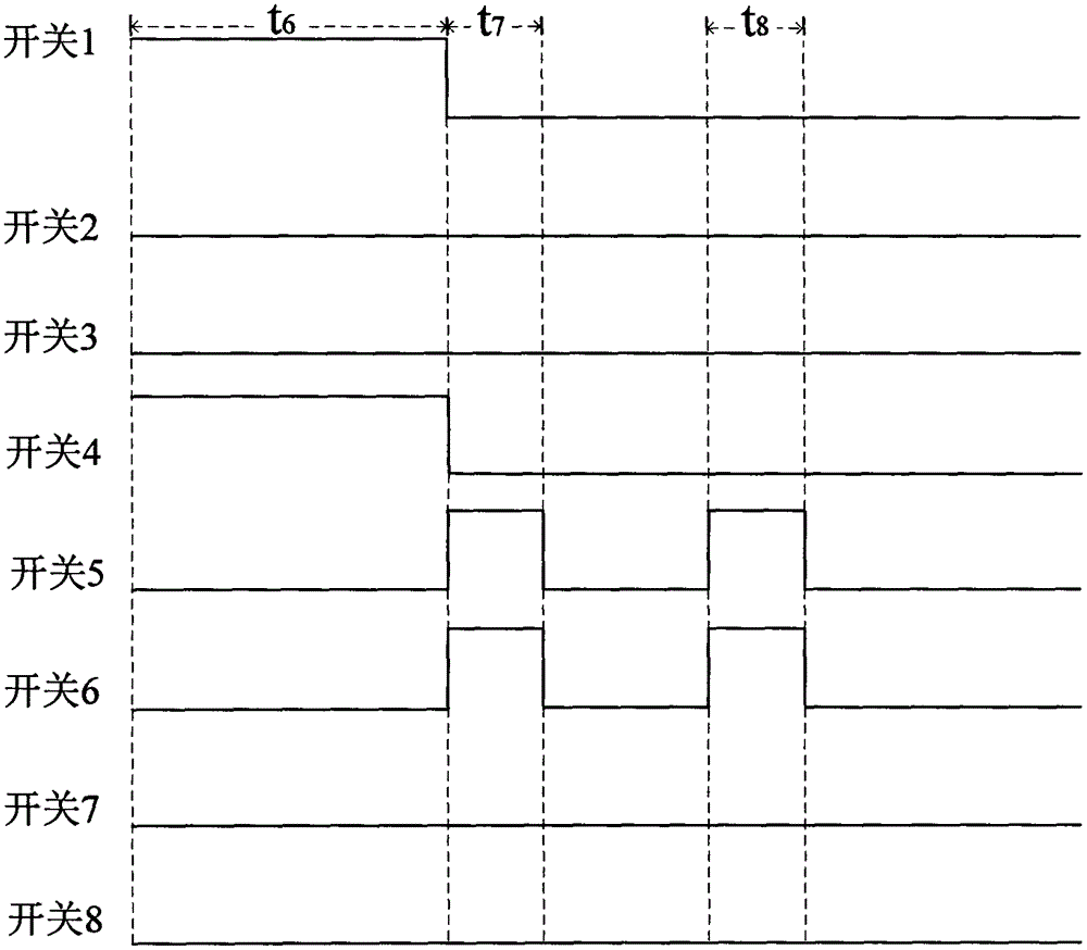
[0043] according to figure 1 and image 3 As shown, after adjusting the resistance of the adjustable resistor R1, the H-bridge circuit is energized, S1 and S4 in the switch module are controlled by the control signal to close, S2, S3, S5, S6, S7, and S8 are disconnected, so that the coil L with impedance passes through Constant current, used to generate a constant magnetic field, the duration of the constant current through the impedance coil L1 is t 6 , where time t 6 should satisfy t 6 >5τ 2 , because the coil with impedance L has inductive reactance, which has the effect of hindering the passage of current in the process of passing current, after 5τ 2 After a period of time, the current flowing through the coil can reach more than 99% of the original current value, tending to a stable state, where τ 2 is the time constant of the RL circuit, and its value is τ 2 =L / R, the curr...

Embodiment 3

[0047] Embodiment 3, an example of generating an alternating magnetic field and saving energy.

[0048] according to figure 1 and Figure 4 As shown, after setting the resistance value of the adjustable resistor R2, the H-bridge circuit is energized, and the combination of S1 and S4 and the combination of S2 and S3 in the switch module are controlled by the control signal for a period of time t 9 Alternately close and open, so that the direction of the current through the coil L will be in the time period t 9 Alternately change, through alternating current, an alternating magnetic field is generated in the coil. When S1 and S4 in the switch module are closed, and S2, S3, S5, S6, S7, and S8 are opened, the current direction in the circuit is as follows: Figure 11 As shown; when S2 and S3 in the switch module are closed, and S1, S4, S5, S6, S7, and S8 are disconnected, the current direction in the circuit is as follows Figure 12 shown.

[0049] When the main circuit is po...


PUM


Abstract

The invention provides an energy-saving control circuit for generating multiple magnetic fields, and particularly provides an energy-saving control circuit for generating multiple magnetic fields based on switch timing control and RLC oscillation. The control circuit comprises a power module, a signal control module, a full H bridge circuit module, a capacitor and a RLC oscillating circuit module provided with an impedance coil, a control switch module and a current limiting resistor. By means of the improvement on the ''energy-saving control circuit for generating multiple magnetic fields based on switch timing control and RLC oscillation'' (Publication No. CN104617840A, publication data: May 13, 2015), the control circuit can not only generate a constant magnetic field and an alternating magnetic field, but also can generate a bipolar pulsed magnetic field, and each working mode has an energy-saving effect. The energy-saving control circuit provided by the invention can generate the multiple magnetic fields through the switch timing control, and the circuit is simple in structure and is convenient to use; and the RLC oscillating circuit can store the electric energy released by the coil after the power down of the control circuit, can recycle the electric energy and an effectively reduce the heat production of the coil.

Description

technical field [0001] The invention provides an energy-saving control circuit for generating various magnetic fields, in particular to an energy-saving control circuit for generating various magnetic fields based on switch sequence control and RLC oscillation. Background technique [0002] With the in-depth study of electromagnetic technology, biomagnetism has also developed, and has been widely used in various fields of life. In the field of biomedicine, the application of magnetic targeted drug delivery technology; in the field of agricultural science and technology, the magnetic treatment technology of alternating magnetic field improves the stress resistance of plants, etc. The energy released by the general magnetic field generation control circuit when the power is turned off is converted into heat energy to heat the coil; the traditional signal generation circuit and power amplifier circuit have complex structures and increase the cost. [0003] Chinese invention pa...

Claims


Application Information

Patent Timeline
IPC IPC(8): H03K3/53H02M1/00
CPCH02M1/00H03K3/53
Inventor 熊慧孙万鹏鹿文龙刘近贞
Owner TIANJIN POLYTECHNIC UNIV
Why Eureka
Try Eureka