Energy-saving control circuit that generates various magnetic fields
An energy-saving control and control circuit technology, which is applied in the direction of electric pulse generator circuit, energy storage element generating pulse, electrical element, etc., and can solve the problems of coil heating and single magnetic field function.
- Summary
- Abstract
- Description
- Claims
- Application Information
AI Technical Summary
Problems solved by technology
Method used
Image
Examples
Embodiment 1
[0035] Embodiment 1, an example of generating a bipolar pulsed magnetic field and saving energy.
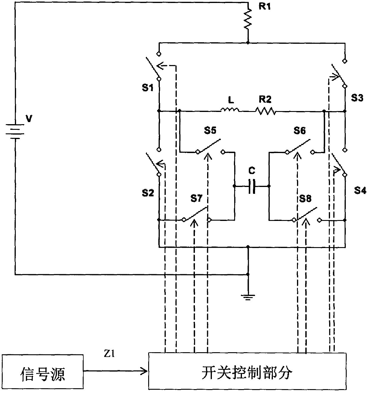
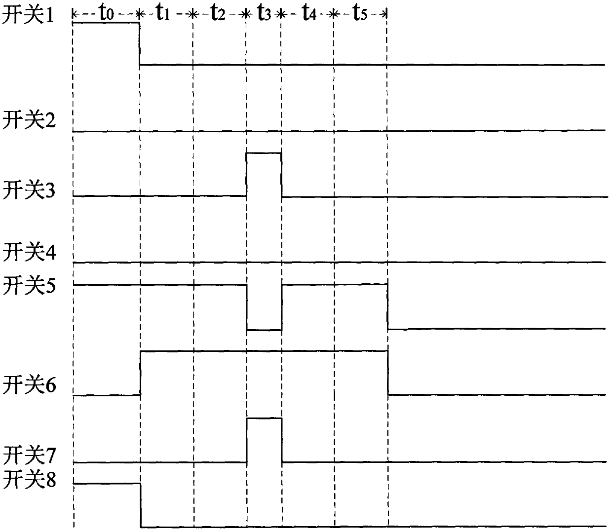
[0036] according to figure 1 and figure 2 As shown, after adjusting the resistance of the adjustable resistor R2, the H-bridge circuit is energized, S1, S5, and S8 in the switch module are controlled by the control signal to close, S2, S3, S4, S6, and S7 are disconnected, and the DC power supply V passes through the resistor R1 Charge the capacitor C for a charging time of t 0 , where t 0 should satisfy t 0 >4.6τ 1 (τ 1 is the RC circuit time constant, τ 1 =R 1 C, R 1 is the resistance value of the adjustable resistor R2, and C is the capacitance value of the capacitor C), because when the charging time of the capacitor is greater than 4.6τ 1 , the voltage across the capacitor reaches 99% of the V voltage of the DC power supply, and it has tended to a stable state, and its current direction is as follows: Figure 5 shown.
[0037] When the capacitor C is fully charged...
Embodiment 2
[0042] Embodiment 2, an example of generating a constant magnetic field and saving energy.
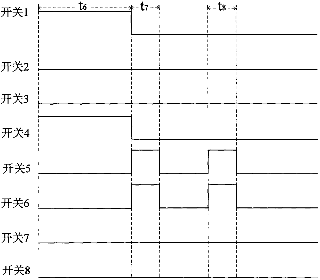
[0043] according to figure 1 and image 3 As shown, after adjusting the resistance of the adjustable resistor R1, the H-bridge circuit is energized, S1 and S4 in the switch module are controlled by the control signal to close, S2, S3, S5, S6, S7, and S8 are disconnected, so that the coil L with impedance passes through Constant current, used to generate a constant magnetic field, the duration of the constant current through the impedance coil L1 is t 6 , where time t 6 should satisfy t 6 >5τ 2 , because the coil with impedance L has inductive reactance, which has the effect of hindering the passage of current in the process of passing current, after 5τ 2 After a period of time, the current flowing through the impedance coil L can reach more than 99% of the original current value, tending to a stable state, where τ 2 is the time constant of the RL circuit, and its value is τ 2 =L...
Embodiment 3
[0047] Embodiment 3, an example of generating an alternating magnetic field and saving energy.
[0048] according to figure 1 and Figure 4 As shown, after setting the resistance value of the adjustable resistor R2, the H-bridge circuit is energized, and the combination of S1 and S4 and the combination of S2 and S3 in the switch module are controlled by the control signal to turn on and off alternately with a time period of t9, so that through the band impedance The current direction of the coil L will alternately change with the time period t9, and the alternating current will generate an alternating magnetic field in the coil L with impedance. When S1 and S4 in the switch module are closed, and S2, S3, S5, S6, S7, and S8 are opened, the current direction in the circuit is as follows: Figure 11 As shown; when S2 and S3 in the switch module are closed, and S1, S4, S5, S6, S7, and S8 are disconnected, the current direction in the circuit is as follows Figure 12 shown.
[...
PUM
 Abstract
Description
Claims
Application Information
 - R&D
- Intellectual Property
- Life Sciences
- Materials
- Tech Scout
- Unparalleled Data Quality
- Higher Quality Content
- 60% Fewer Hallucinations
Browse by: Latest US Patents, China's latest patents, Technical Efficacy Thesaurus, Application Domain, Technology Topic, Popular Technical Reports.
© 2025 PatSnap. All rights reserved.Legal|Privacy policy|Modern Slavery Act Transparency Statement|Sitemap|About US| Contact US: help@patsnap.com


