

Differential voltage absolute value circuit
An absolute value circuit and differential voltage technology, applied in electrical components, pulse processing, pulse shaping, etc., can solve problems such as poor performance of voltage absolute value circuits, and achieve the effect of small quantity and simple structure
- Summary
- Abstract
- Description
- Claims
- Application Information
AI Technical Summary
Problems solved by technology
Method used
Image

Examples
Embodiment Construction
[0020] It can be seen from the background art that the differential absolute value circuit formed in the prior art has poor performance.
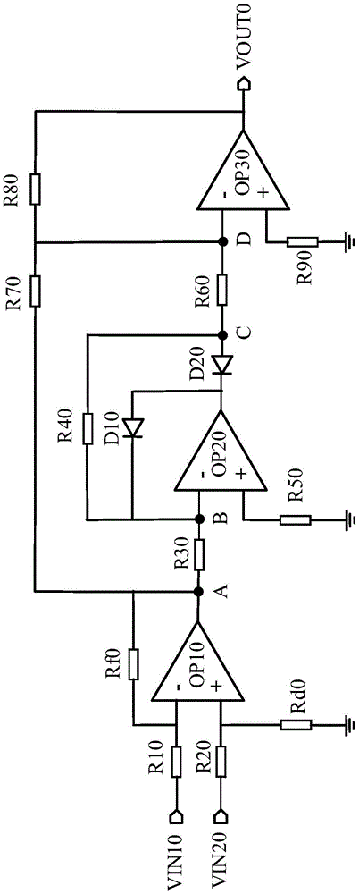
[0021] The inventors of the present invention have studied the differential absolute value circuit in the prior art, and found that the differential absolute value circuit in the prior art has problems such as complex structure, dual power supply, and large error. Specifically, refer to figure 1 , figure 1 A schematic structural diagram of a differential absolute value circuit in the prior art is shown. The op amp OP10 and the resistors R10, R20, Rf0 or Rd0 form a voltage difference circuit, and the two input voltages VIN10 and VIN20 are respectively input through the resistors R10 and R20 and the inverting input and non-inverting input of the op amp OP10; the voltage at point A V ( A ) = ( R 20 / / ...
PUM
 Abstract
Description
Claims
Application Information