Toroidal field coil for use in a fusion reactor

A field coil and reactor technology, used in fusion reactors, thermonuclear fusion reactors, nuclear reactors, etc., can solve the problems of complex fusion energy challenges

Active Publication Date: 2016-06-01
TOKAMAK ENERGY
View PDF5 Cites 13 Cited by
  • Summary
  • Abstract
  • Description
  • Claims
  • Application Information

AI Technical Summary

Problems solved by technology

[0002] The challenges of generating fusion energy are complex
Many alternatives to the tokamak have been proposed, although none have yet produced any results comparable to the best currently operating tokamaks such as JET

Method used


Image

  • Toroidal field coil for use in a fusion reactor
  • Toroidal field coil for use in a fusion reactor
  • Toroidal field coil for use in a fusion reactor

Examples


Embodiment Construction

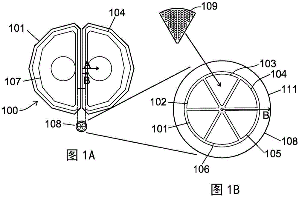
[0029] The present application is based on a very compact form of tokamak and employs a series of innovative features, including the use of high temperature superconducting magnets. The "Efficient Compact Fusion Reactor" (ECFR) aims to provide a compact fusion power plant.

[0030] When a deuterium-tritium (D-T) or deuterium-deuterium (D-D) plasma becomes very hot, nuclei fuse together, producing fusion neutrons and releasing high-energy neutrons. So far, the most promising way to achieve this goal is to use a tokamak; in polymerization using conventional tokamak schemes (as implemented by ITER), the plasma needs to have high confinement time, high temperature and high density to optimize this process.

[0031] Tokamak is based on a strong circular magnetic field B T , high plasma current I p is characterized by a combination of large plasma volumes and significant auxiliary heating to provide a thermally stable plasma that enables fusion to occur. Auxiliary heating (e.g. ...


PUM


Abstract

Disclosed herein is a toroidal field coil for generating a toroidal magnetic field in a nuclear fusion reactor comprising a toroidal plasma chamber having a central column, the toroidal field coil comprising a plurality of windings passing through the central column and around the outside of the plasma chamber. Each winding includes a cable comprising a plurality of stacked HTS tapes, each HTS tape including one or more layers of a high temperature superconductor material. The HTS tapes are arranged such that a face of each HTS tape is parallel to the toroidal magnetic field as the cable passes through the centre column.

Description

technical field [0001] The present application relates to compact fusion reactors operating in strong toroidal fields. In particular, but not exclusively, the invention relates to a spherical tokamak reactor suitable for use as an energy source or as a high-efficiency neutron source and having a plasma confinement system comprising high temperature superconductor (HTS) coils. Background technique [0002] The challenges of generating fusion energy are complex. Many alternatives to the tokamak have been proposed, although none have yet produced any results comparable to the best currently operating tokamaks such as JET. [0003] After the construction of the largest and most expensive (cl5bn euro) tokamak ITER ever started, the world's nuclear fusion research has entered a new stage. A successful route to commercial fusion reactors requires long pulses, stable operation combined with high efficiencies to make electricity generation economical. These three conditions are pa...

Claims


Application Information

Patent Timeline
Patent Type & Authority Applications(China)
IPC IPC(8): G21B1/05
CPCH05H1/12G21B1/057Y02E30/10H01F6/06G21B1/05
Inventor 阿兰·赛克斯米哈尔·格瑞亚耐维奇大卫·金厄姆大卫·霍克沃斯齐亚德·赫尔曼斯蒂文·波尔
Owner TOKAMAK ENERGY
Why Eureka
Try Eureka