
Dust collection device for loading of bagged cement

A dust removal device and cement technology, applied in the direction of dust removal, cleaning methods and appliances, chemical instruments and methods, etc., can solve the problems of unsatisfactory dust removal effect, far away dust escape point, poor safety performance, etc., to reduce investment costs and Operating costs, cost savings and operating costs, and the effect of ensuring safe operations

Active Publication Date: 2016-06-08
SICHUAN XINGUANGDA ENVIRONMENTAL PROTECTION EQUIP CO LTD
View PDF10 Cites 3 Cited by
  • Summary
  • Abstract
  • Description
  • Claims
  • Application Information

AI Technical Summary

Problems solved by technology

[0004] However, due to the different heights of the transport vehicles, in the actual use process, the dust collection cover can only move back and forth along the track direction with the loading machine trolley, resulting in a long distance from the dust escape point. Therefore, the existing dust removal device has a processing air volume Disadvantages of large size, high investment, high fan energy consumption, unsatisfactory dust removal effect and poor safety performance

Method used


Image

  • Dust collection device for loading of bagged cement
  • Dust collection device for loading of bagged cement
  • Dust collection device for loading of bagged cement

Examples


Embodiment 1

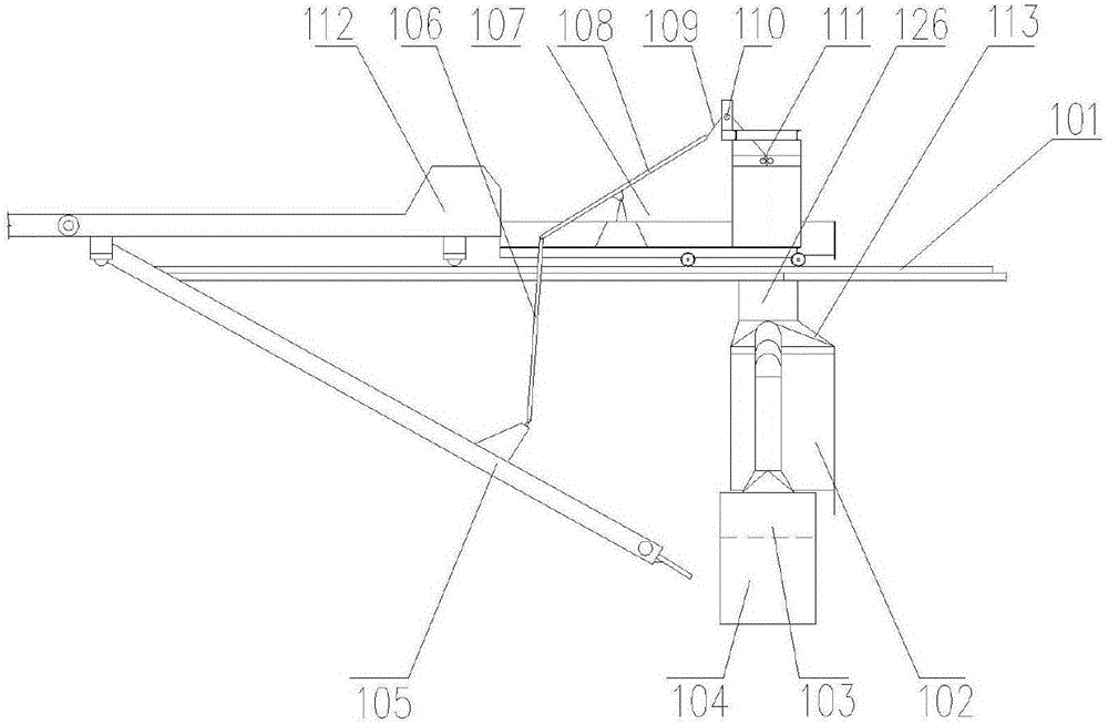
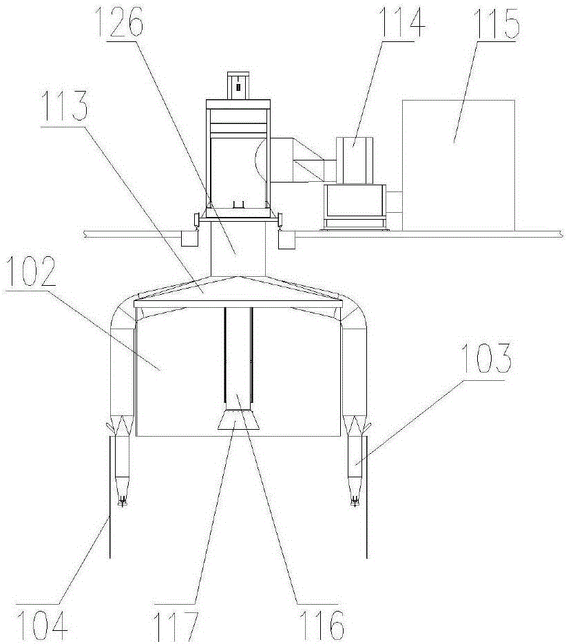
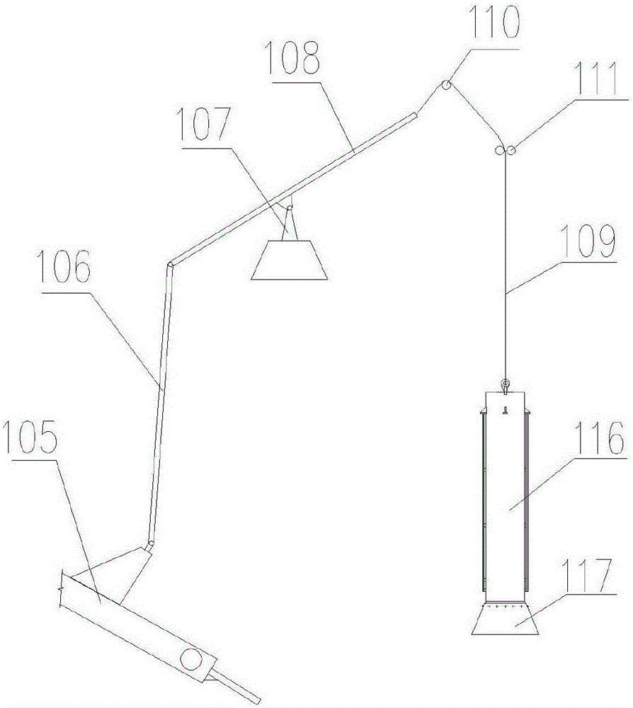
[0049] This embodiment provides a dust removal device for bagged cement loading, which includes: a top dust suction cover 113, a main air inlet pipe 126, a suction duct 116 and a lifting assembly; the top dust suction cover 113 is arranged on the main inlet At the air inlet of the air duct 126; the suction duct 116 is slidably arranged in the main air intake duct 126, and is connected with the lifting assembly, and the suction duct 116 is controlled by the lifting assembly to move up and down along the inner side wall of the main air intake duct 126; the top Both the dust collection hood 113 and the air suction duct 116 communicate with the main air inlet pipe 126 ; the lifting assembly is connected with the air suction duct 116 .

[0050] like Figure 1-2 As shown, the above-mentioned dust removal device forms a dust removal system with the existing car loader and pulse bag filter 115, wherein the car loader includes: guide rail 101, car loader trolley 112, conveyor belt brac...

Embodiment 2

[0060] In this embodiment, improvements are made to the air suction duct 116 and the side dust suction hood 103 of the dust removal device described in Embodiment 1, respectively.

[0061] like Figure 4 As shown, the air inlet of the suction duct 116 is provided with a trumpet-shaped windshield 117, and the windshield 117 is connected with the air inlet of the suction duct 116 through a telescopic tube 118, thereby not only helping the suction duct 116 to absorb dust, And more practical requirements, the windshield 117 can be adjusted through the telescopic tube 118 .

[0062] Wherein, in order to facilitate the connection between the connecting wire 109 and the air suction duct 116 , a connection ring 120 is provided outside the top of the air suction duct 116 .

[0063] like Figure 5 As shown, according to actual usage requirements, in order to facilitate the adjustment of the wind direction of the side dust collection hoods 103 , louvers 121 are provided at the air inle...


PUM


Abstract

The invention provides a dust collection device for loading of bagged cement, and belongs to the technical field of dust collection. The dust collection device comprises a top dust sucking cover, a main air inlet tube, an air sucking guide tube and a lifting component, wherein the lifting component is used for adjusting the air sucking guide tube to ascend and descend; the top dust sucking cover is arranged at the air inlet of the main air inlet tube; the air sucking guide tube is arranged inside the main air inlet tube in a sliding manner; the top dust sucking cover and the air sucking guide tube are respectively communicated with the main air inlet tube; the lifting component is connected with the air sucking guide tube. By adopting the dust collection device, dust diffused in loading can be effectively removed, the energy can be saved, the cost can be lowered, the operation security of operators can be ensured, and moreover the application range can be widened as the dust collection device is applicable to vehicles of different heights and dust collection of similar loading operation.

Description

technical field [0001] The invention relates to the technical field of dust removal, in particular to a dust removal device for loading bagged cement into trucks. Background technique [0002] When cement is loaded, not only the loading machine needs to move back and forth, but also up and down, which is easy to generate dust and disperse in the working environment. Due to the wide range and dispersion of dust sources, cement manufacturers have to control the dust on the production line. It is difficult, and a better solution has not been found for many years. [0003] At present, the dust removal work of cement bag loading is mainly completed through the dust collection hood arranged at the end of the car loading machine and the car loading machine. [0004] However, due to the different heights of the transport vehicles, and in the actual use process, the dust collection cover can only move back and forth along the track direction with the loading machine trolley, resulti...

Claims


Application Information

Patent Timeline
IPC IPC(8): B08B15/02B08B15/04
CPCB08B15/02B08B15/04
Inventor 杨春雒贵坤
Owner SICHUAN XINGUANGDA ENVIRONMENTAL PROTECTION EQUIP CO LTD
Learn More