Rapid mounting and dismounting structure as well as expansion tube and expansion head assembly comprising same

A fast and expanding tube technology, applied in the connection of rods, connecting components, quick-acting fasteners, etc., can solve the problems of easy damage, trouble, and unfavorable replacement of the expanding ball, so as to achieve low cost and improve production efficiency. , The effect of convenient production and processing

Inactive Publication Date: 2016-06-08
OMS MASCH CO LTD
View PDF3 Cites 8 Cited by
  • Summary
  • Abstract
  • Description
  • Claims
  • Application Information

AI Technical Summary

Problems solved by technology

[0002] The tube expansion process is a process in which the tube expansion tool is squeezed into the copper tube by an external force to expand the diameter of the steel tube, and the tube expansion tool is generally composed of an expansion rod and an expansion ball installed on the expansion rod and having a diameter larger than the inner diameter of the steel pipe. There are generally two ways to connect the rod and the expansion ball: one is welding, but welding is not conducive to the replacement of the expansion ball, because it is necessary to replace different types of expansion balls when expanding pipes with different diameters and specifications, or to expand during use. The ball is easily damaged and needs to be replaced
The other uses a threaded structure for connection to realize the replacement of the swelling ball, but the threaded connection structure is still too troublesome for the swelling ball that needs to be replaced frequently

Method used


Image

  • Rapid mounting and dismounting structure as well as expansion tube and expansion head assembly comprising same
  • Rapid mounting and dismounting structure as well as expansion tube and expansion head assembly comprising same
  • Rapid mounting and dismounting structure as well as expansion tube and expansion head assembly comprising same

Examples


Embodiment Construction

[0028] The technical features of the present invention will be further described in detail below in conjunction with the accompanying drawings to facilitate the understanding of those skilled in the art.

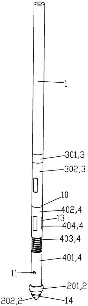
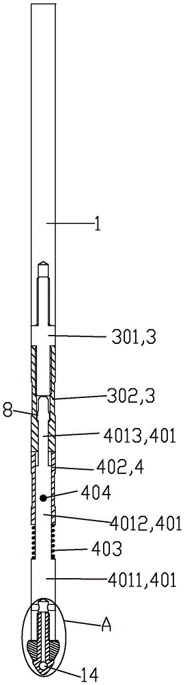
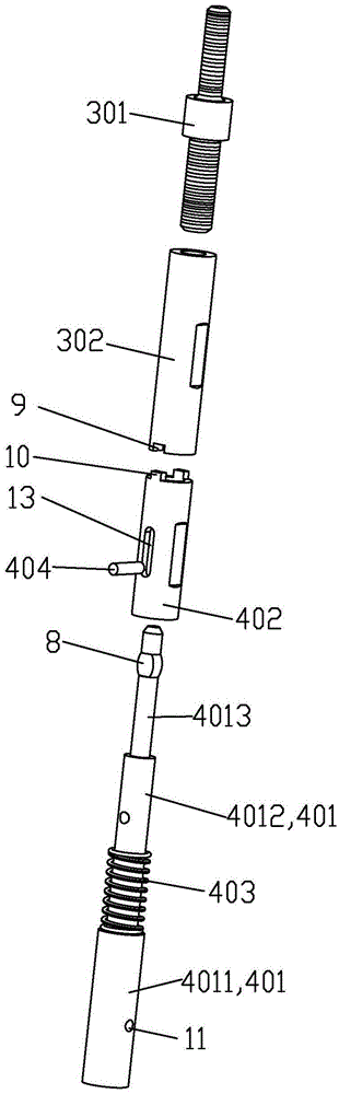
[0029] In the existing design, the first part 1 and the second part 2 are directly fixed by threaded connection, but because the second part 2 needs to be replaced frequently during the processing, the production efficiency is low due to troublesome disassembly and assembly. And a kind of quick disassembly structure designed by the present invention, such as Figure 1 to Figure 7 As shown, it includes a first connection assembly 3 connected to the first part 1 and a second connection assembly 4 connected to the second part 2. The first connection assembly 3 is provided with a 4, the card table 7 is formed at the junction of two different holes. The second connection assembly 4 is clamped by the card table 7 to realize the quick disassembly and assembly of the second connect...


PUM


Abstract

The invention discloses a rapid mounting and dismounting structure as well as an expansion tube and expansion head assembly comprising the same. According to the technical scheme, the rapid mounting and dismounting structure is characterized by comprising a first connection assembly connected with a first component and a second connection assembly connected with a second component, wherein a clamping table capable of clamping the second connection assembly is arranged on the first connection assembly and formed in the position where two different holes are connected. The first component is an expansion tube while the second component is an expansion head assembly. During mounting, all that is required is to insert an inserting shaft part of the second connection assembly into outer and inner holes of the first connection assembly and rotate for a certain angle, then the second connection assembly can be clamped on the clamping table, meanwhile, under the press of a spring and the action of a positioning table, the second connection assembly cannot loose, during dismounting, all that is required for pulling the inserting shaft part out of the inner and outer holes quickly is to rotate the second connection assembly, rapid mounting and dismounting are realized, and the production efficiency is improved.

Description

【Technical field】 [0001] The invention relates to a quick disassembly structure and an expander with the disassembly structure. 【Background technique】 [0002] The tube expansion process is a process in which the tube expansion tool is squeezed into the copper tube by an external force to expand the diameter of the steel tube. The tube expansion tool is generally composed of an expansion rod and an expansion ball installed on the expansion rod with a diameter larger than the inner diameter of the steel pipe. There are generally two ways to connect the rod and the expansion ball: one is welding, but welding is not conducive to the replacement of the expansion ball, because it is necessary to replace different types of expansion balls when expanding pipes with different diameters and specifications, or the expansion during use. The ball is easily damaged and needs to be replaced. The other uses a threaded structure for connection to realize the replacement of the bulging ball...

Claims


Application Information

Patent Timeline
Patent Type & Authority Applications(China)
IPC IPC(8): B21D39/08F16B21/04F16B21/08F16B7/20
CPCB21D39/08F16B7/20F16B21/04F16B21/08
Inventor 龙晓明黄晓成
Owner OMS MASCH CO LTD
Why Eureka
Try Eureka