Engraving and milling machine tool with servo magazine

A technology for tool magazines and machine tools, which is applied to metal processing machinery parts, clamping, and supports, and can solve the problems of increased production costs, prolonged tool change time, and low tool change efficiency, achieving low production costs and improved tool change efficiency , the effect of a reasonable structure

Inactive Publication Date: 2016-06-08
赛佳智能科技(中山)有限公司
View PDF12 Cites 11 Cited by
  • Summary
  • Abstract
  • Description
  • Claims
  • Application Information

AI Technical Summary

Problems solved by technology

[0006] It can be seen from the above that the current engraving and milling machine tools have the following disadvantages: 1. The actions of these three mechanisms are relatively complicated, and it takes a long time during the entire tool change process, resulting in low tool change efficiency; 2. Due to the swing of the manipulator and the The overturning action and the translational movement of the cutter head all require a large space to complete, resulting in the current engraving and milling machine tools taking up a relatively large space and increasing production costs; 3. In addition, if figure 1 , 2 As shown, due to the use of ordinary motors, the positioning boss 101 and the positioning groove 201 are respectively provided on the clamping fixture 10 and the handle 20, so that it takes a long time to position the positioning boss 101 and the positioning groove 201 before changing the tool. Groove 201, and then the tool holder can be assembled and disassembled, which will further lengthen the tool change time

Method used


Image

  • Engraving and milling machine tool with servo magazine
  • Engraving and milling machine tool with servo magazine
  • Engraving and milling machine tool with servo magazine

Examples


Embodiment Construction

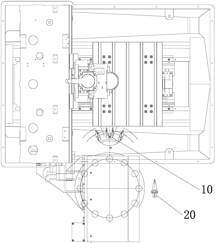
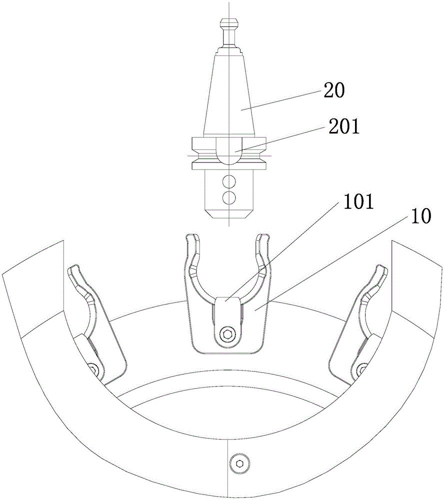
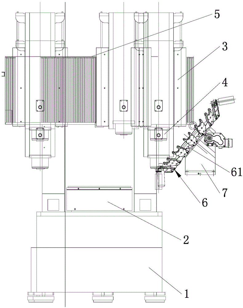
[0020] An engraving and milling machine with a servo tool magazine, such as Figures 3 to 7 As shown, it includes a base 1, a workbench 2, a main shaft machine 3, a main shaft 4 installed on the main shaft machine 3, a machine base 5 for installing the main shaft machine 3, and a tool magazine 6. Here, the tool magazine 6 is obliquely installed on the cutter head support slope of the cutter head support seat 7; Several sets of knife claw groups 62 on the periphery of the rotating disk 61, the handle of a knife 63 with a milling cutter clamped on the knife claw group 62, all handles of a knife 63 are installed on the knife claw group 62 to form a tool magazine; The set of claws 62 at the bottom of the tool magazine 6 is in a horizontal position, so that the tool handle it clamps is in a vertical state so that the main shaft 4 can move in and out of the claws horizontally in the direction of the X axis, and lift the rear sleeve in the direction of the Z axis. Put in the handle ...


PUM


Abstract

The invention discloses an engraving and milling machine tool with a servo magazine. The engraving and milling machine tool is characterized in that the magazine is obliquely mounted on a cutter head supporting oblique plane of a cutter head supporting seat, faces a spindle and comprises a turntable, a plurality of sets of jaw groups and shanks, the turntable is parallelly mounted on the cutter head supporting oblique plane of the cutter head supporting seat, the multiple sets of jaw groups are circularly distributed at the peripheral edge of the turntable, and the shanks with milling cutters are clamped on the jaw groups; the set of jaw groups at the lowermost end of the magazine is positioned at a horizontal location. The engraving and milling machine tool has the advantages that the magazine can easily avoid cutter shafts when rotating, the jaw groups can be horizontally shifted after the shanks are mounted on or detached from the cutter shafts in the vertical directions, accordingly, the magazine only needs to rotate on the cutter head supporting oblique plane of the cutter head supporting seat in integral cutter changing procedures and can avoid the cutter shafts without translating in the X-axis direction, cutters can be changed without large spaces, and the integral engraving and milling machine tool is compact in integral structure and small in occupied space; the integral cutter changing procedures are simple, the cutter changing time can be greatly shortened, accordingly, the engraving and milling machine tool is reasonable in structure and low in production cost, and the cutter changing efficiency can be greatly improved.

Description

technical field [0001] The invention relates to a numerical control machine tool, in particular to an engraving and milling machine tool with a servo tool magazine. Background technique [0002] In order to facilitate the replacement of milling cutters and improve the efficiency of tool change, people often install tool magazines on engraving and milling machines. The tool magazine of the current engraving and milling machine tool is a horizontally placed cutterhead, and each tool holder with a milling cutter in the cutterhead is inserted vertically into the cutterhead, so that an additional manipulator is required to grab it when replacing it. The tool handle on the tool shaft is returned to the tool magazine first, and then the tool handle with the desired tool number is grabbed by the manipulator and put back on the tool shaft. Before returning the tool and taking a new tool, the three mechanisms need to be Do as follows: [0003] 1. The tool axis needs to move in trans...

Claims


Application Information

Patent Timeline
Patent Type & Authority Applications(China)
IPC IPC(8): B23Q3/157
CPCB23Q3/15706
Inventor 徐新华匡宗军匡宗发刘建军
Owner 赛佳智能科技(中山)有限公司
Why Eureka
Try Eureka