
Machining method for plastic movable composite member

A processing method and technology for moving parts, applied in the direction of coating, etc., can solve the problems of mutual rotation stuck, inconvenient use by customers, deformation of assemblies, etc., and achieve the effect of high product quality, smooth movement and stable performance.

Inactive Publication Date: 2016-06-08
GUANGZHOU KYOKUTO ELECTRONICS LTD +1
View PDF6 Cites 3 Cited by
  • Summary
  • Abstract
  • Description
  • Claims
  • Application Information

AI Technical Summary

Problems solved by technology

[0003] However, this assembly method will lead to deformation of the assembly during the assembly process, resulting in unstable product quality; in severe cases, it may even cause a sense of stagnation when they rotate with each other, affecting product quality and bringing inconvenience to customers

Method used


Image

  • Machining method for plastic movable composite member
  • Machining method for plastic movable composite member
  • Machining method for plastic movable composite member

Examples


Embodiment 1

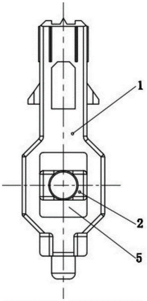
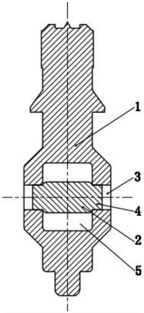
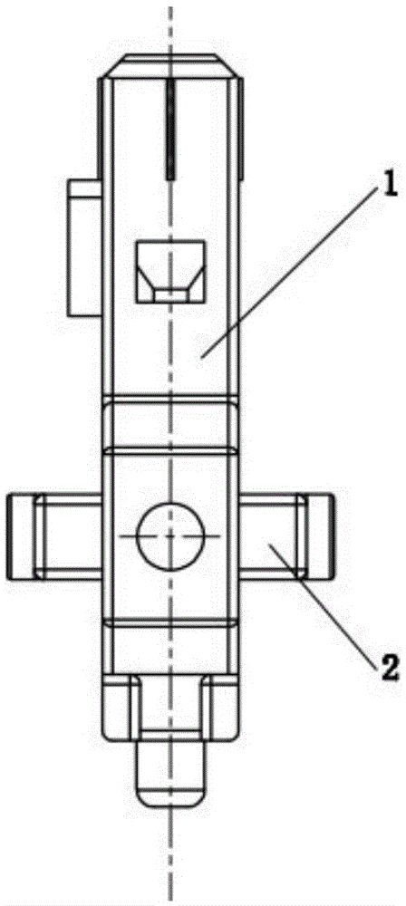
[0029] A processing method of a plastic movable assembly of the present invention, its specific implementation is described in terms of a processing method of a four-way cross shaft assembly, such as Figures 1 to 4 shown. It includes the following steps:

[0030] (1) Injection molding step of the first movable part: the first material is PA66GF30, and its molding shrinkage rate is 0.5%; the first material required for molding the first movable part 1 is heated to above 270-290°C to make it into a liquid state , and then injected into the first mold;

[0031] (2) Cooling step of the first movable part: cooling the first material in the first mold to form the first movable part 1; the first movable part 1 is the first shaft of the four-way cross shaft assembly, wherein A through hole 5 is opened at the top; the cross-sectional shape of the through hole 5 is a rectangle, and a limiting hole 3 is respectively arranged on the two side walls parallel to the axial direction of the...


PUM


Abstract

The invention discloses a machining method for a plastic movable composite member. The machining method comprises the following steps of injection molding of a first movable piece, cooling of the first movable piece, demolding of the first movable piece, injection molding of a second movable piece, cooling of the second movable piece and demolding of the second movable piece. According to the machining method for the plastic movable composite member, the connected movable pieces in the formed composite member can relatively move, movement is smooth, no clamping sense is generated, the performance is stable, and the product quality is high.

Description

technical field [0001] The invention relates to the field of injection molding, in particular to a processing method for a plastic movable assembly. Background technique [0002] At present, a four-way cross shaft assembly is used in the four-way adjustment switch in the car seat switch, which is assembled from two relatively rotatable first movable parts and second movable parts. Wherein, the first movable part is provided with a rectangular through hole, and the two opposite inner walls of the rectangular through hole are respectively provided with a circular limiting hole; Round limit block. When assembling, the production personnel pass the second movable part through the rectangular through hole on the first movable part, and let the circular limit block cooperate with the circular limit hole, so as to move the first movable part and the second movable part connect. [0003] However, this assembly method will lead to deformation of the assembly during the assembly pr...

Claims


Application Information

Patent Timeline
IPC IPC(8): B29C45/14B29K77/00B29K59/00
CPCB29C45/0017B29C45/0001B29C45/14467B29K2059/00B29K2077/00
Inventor 李俊强李荣生陈佳杨小勇周文军
Owner GUANGZHOU KYOKUTO ELECTRONICS LTD
Learn More