Vibration control method and device for ornithopter

A technology of flapping aircraft and boundary control rate, which is used in the control of starting methods, aircraft, motor vehicles, etc.

Active Publication Date: 2016-06-08
UNIV OF SCI & TECH BEIJING
View PDF3 Cites 19 Cited by
  • Summary
  • Abstract
  • Description
  • Claims
  • Application Information

AI Technical Summary

Problems solved by technology

[0004] The technical problem to be solved by the present invention is to provide a vibration control method and device for flapping wing aircraft, which can effectively suppress the deformation of flexible wings caused by external disturbances

Method used


Image

  • Vibration control method and device for ornithopter
  • Vibration control method and device for ornithopter
  • Vibration control method and device for ornithopter

Examples


Embodiment Construction

[0222] In order to make the technical problems, technical solutions and advantages to be solved by the present invention more clear, the following will be described in detail with reference to the accompanying drawings and specific embodiments.

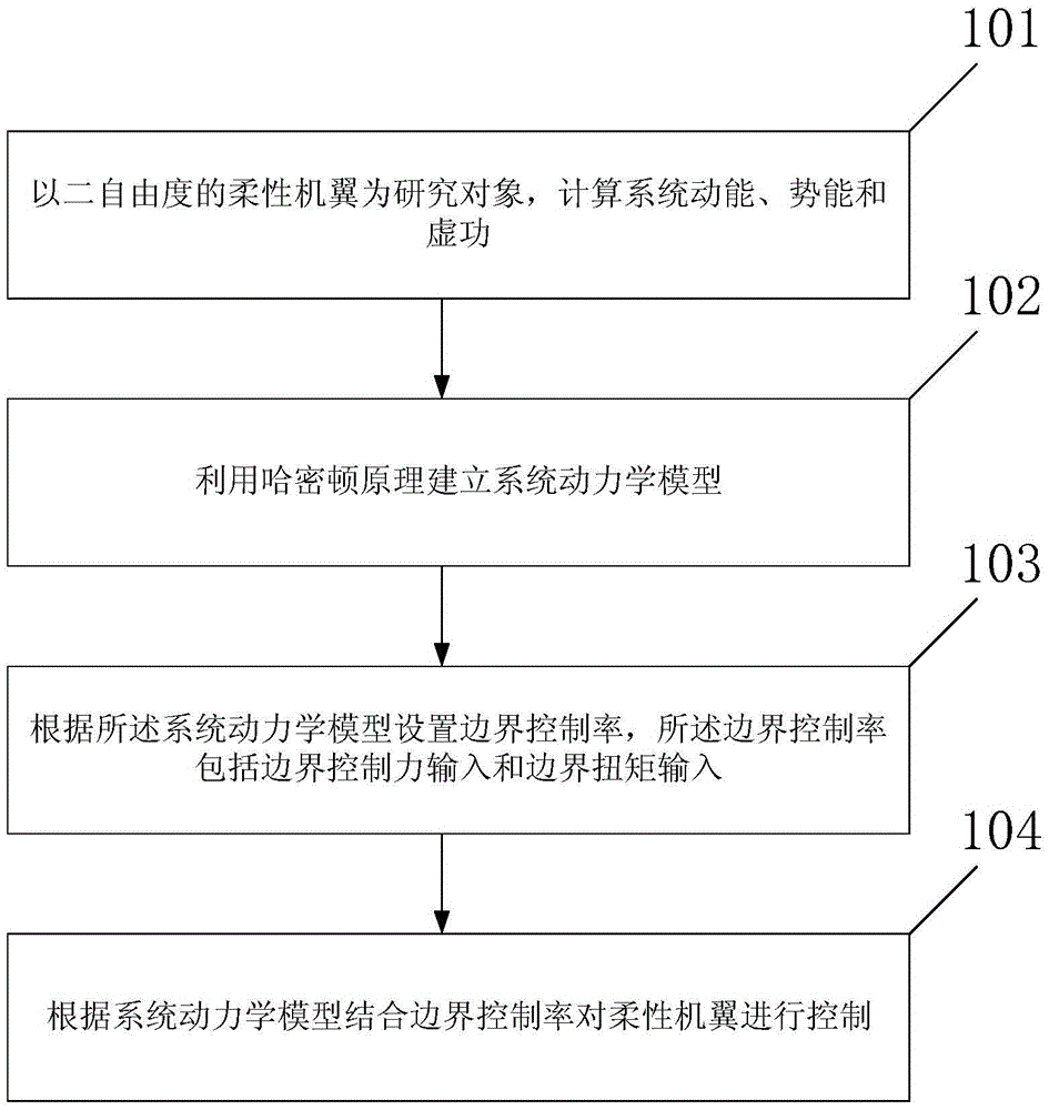
[0223] like figure 1 As shown, a kind of vibration control method for flapping aircraft according to the embodiment of the present invention, described vibration control method for flapping aircraft comprises:

[0224] Step 101: Taking the flexible wing with two degrees of freedom as the research object, calculate the kinetic energy, potential energy and virtual work of the system.

[0225] Step 102: Establish a system dynamics model by using Hamilton's principle.

[0226] Step 103: Set a boundary control rate according to the system dynamics model, the boundary control rate includes F(t) and M(t), where F(t) is the boundary control force input, and M(t) is the boundary torque enter.

[0227] Guarantee 104: The flexible wing is con...


PUM


Abstract

The invention provides a vibration control method and device for an ornithopter. The method comprises the following steps: by taking a flexible wing with two-degree of freedom as a research object, calculating system kinetic energy, potential energy and virtual work; constructing a system dynamics model by using a Hamilton's principle; setting a boundary control rate according to the system dynamics model, wherein the boundary control rate comprises F(t) and M(t), the F(t) is boundary control force input, and the M(t) is boundary torque input; controlling the flexible wing according to the system dynamics model and the boundary control rate. By constructing the system dynamics model by using the Hamilton's principle, and setting the boundary control rate according to the system dynamics model, a situation that distributed disturbance exists at a boundary is fully considered, and flexible wing deformation caused by external disturbance is effectively inhibited.

Description

technical field [0001] The invention relates to the technical field of automatic control, in particular to a vibration control method and device for a flapping-wing aircraft. Background technique [0002] In recent years, with the continuous increase of people's demand for UAV technology and the rapid development of advanced manufacturing technology, new material technology and new energy technology, the research on micro-flying machines has become a technological hotspot. In 1992, at a seminar on future military technology, the US Defense Advanced Research Projects Agency first proposed the concept of a relatively complete Micro Air Vehicle (MAV, MicroAirVehicles). MAVs are a versatile category of drones that can be used to inspect, monitor, or search for targets in specific environments. [0003] Due to the increased demand for UAVs for both military and civilian use, designers have sought to reduce the weight of UAVs while increasing the operability of the system. As a ...

Claims


Application Information

Patent Timeline
Patent Type & Authority Applications(China)
IPC IPC(8): B64C33/02
CPCB64C33/02B64C13/16
Inventor 贺威陈宇楠吕垌孙长银
Owner UNIV OF SCI & TECH BEIJING
Why Eureka
Try Eureka