
Open-loop control method for rotation speed change of reaction wheels and unloading method

A reaction wheel and rotational speed change technology, which is applied in attitude control, space navigation equipment, space navigation equipment, etc., can solve the problems affecting flywheel attitude control and maintaining flywheel speed, so as to achieve flexible and convenient use, ensure correctness, and simplify design Effect

Inactive Publication Date: 2016-06-08
SHANGHAI ENG CENT FOR MICROSATELLITES
View PDF6 Cites 23 Cited by
  • Summary
  • Abstract
  • Description
  • Claims
  • Application Information

AI Technical Summary

Problems solved by technology

[0003] Using 4 flywheels for attitude control, the flywheels can be biased near the nominal speed to form zero momentum. For the torque control mode, the speed of the reaction flywheel will decrease under the action of friction torque. When the speed of the four reaction wheels decreases at the same time, It can also ensure stable attitude and zero momentum throughout the star, that is, it is impossible to maintain the flywheel speed through attitude closed-loop feedback. Therefore, to keep the flywheel near the nominal speed requires friction compensation for each flywheel, but because the friction torque of each flywheel is different , the compensation torque causes the nominal speed of the flywheel to be different, which affects the attitude control of the flywheel

Method used

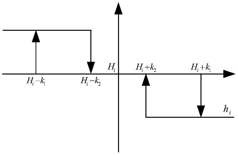
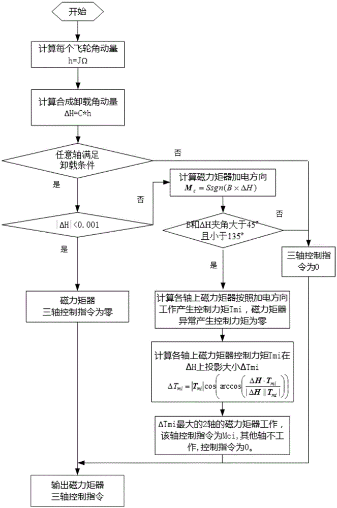
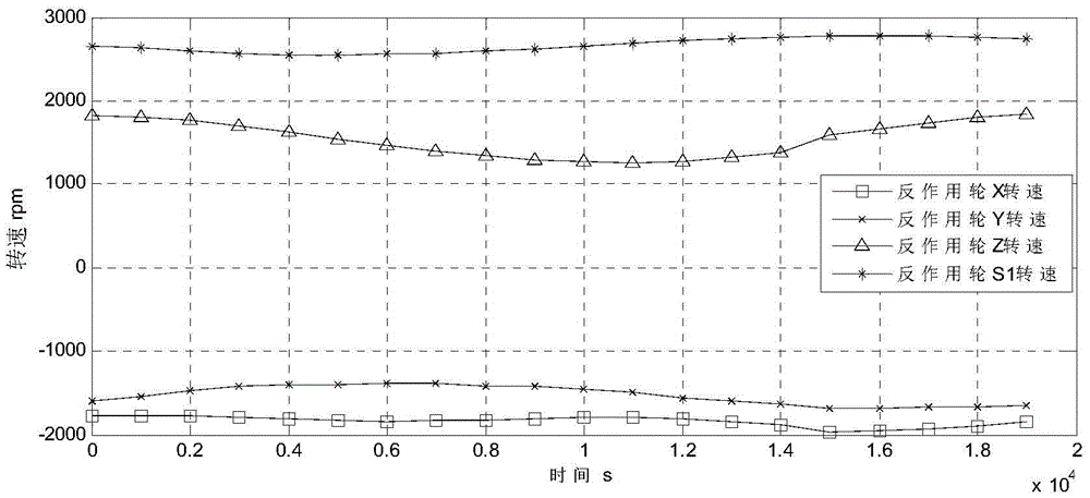

Image

  • Open-loop control method for rotation speed change of reaction wheels and unloading method
  • Open-loop control method for rotation speed change of reaction wheels and unloading method
  • Open-loop control method for rotation speed change of reaction wheels and unloading method

Examples


Embodiment Construction

[0011] The specific implementation of the method provided by the present invention will be described in detail below in conjunction with the accompanying drawings.

[0012] Step 1: Four flywheels including the first flywheel, the second flywheel, the third flywheel and the fourth flywheel are used for control, and the control torque command of the fourth flywheel is adjusted to be consistent with the friction torque of the theoretical nominal speed.

[0013] In this step, the friction torque T is obtained according to the nominal speed of the fourth flywheel f4 , and perform friction torque compensation on it to obtain the reaction wheel control command T wc4 :

[0014] T wc4 =-T f4

[0015] And the reaction wheel torque control voltage:

[0016] u wc4 =T wc4 / k i4

[0017] Among them, k i4 is the fourth flywheel moment coefficient.

[0018] When in orbit, the friction torque can be increased or decreased according to the change of the speed of the fourth flywheel, ...


PUM


Abstract

The invention provides an open-loop control method for the rotation speed change of reaction wheels (hereinafter referred to as flywheels) and an unloading method. The open-loop control method for the rotation speed change of the reaction wheels and the unloading method comprise the following specific steps that 1, controlling is conducted through the four flywheels, and the instruction of the magnitude of the reaction wheel control torque of the fourth flywheel is adjusted to be consistent with the magnitude of the theoretical nominal rotation speed friction torque; 2, a control instruction output by a controller is limited within the maximum output torque, the control torque of each flywheel is distributed according to a flywheel distribution matrix, after the control torque of each flywheel is distributed, the flywheel with the maximum output torque is limited within the maximum torque, and the control torque of the other two flywheels is decreased and increased proportionally; 3, the momentum of a synthetic angle of the four flywheels is calculated, and when any axial angle momentum reaches the unloading threshold range and the relationship between the magnetic field intensity and an angular momentum included angle during unloading is met, magnetic torquers are started to be uninstalled; and 4, the magnetic torquer with the maximum unloading capacity is selected to work, and the flywheels are unloaded by adopting a switch control mode.

Description

technical field [0001] The invention relates to the technical field of aerospace control, in particular to an open-loop control method for changing the rotational speed of a reaction wheel and unloading it. Background technique [0002] The reaction wheel is a common actuator for satellites. Due to the higher and higher requirements for satellite attitude accuracy and satellite life, the reaction wheel should be controlled to work near the optimum operating speed when performing attitude control to avoid excessive speed. Zero interference affects attitude accuracy while improving lifespan. [0003] Using 4 flywheels for attitude control, the flywheels can be biased near the nominal speed to form zero momentum. For the torque control mode, the speed of the reaction flywheel will decrease under the action of friction torque. When the speed of the four reaction wheels decreases at the same time, It can also ensure stable attitude and zero momentum throughout the star, that is,...

Claims


Application Information

Patent Timeline
IPC IPC(8): B64G1/24G05D1/08
CPCB64G1/24B64G1/244
Inventor 白涛熊淑杰武国强秦贵军颜艳腾
Owner SHANGHAI ENG CENT FOR MICROSATELLITES
Learn More