Water draining groove

A drainage channel and water flow technology, applied in soil protection, construction, infrastructure engineering, etc., can solve problems such as unsatisfactory drainage effect, sand damage, cumbersome steps, etc.

Inactive Publication Date: 2016-06-08
HOHAI UNIV
View PDF6 Cites 1 Cited by
  • Summary
  • Abstract
  • Description
  • Claims
  • Application Information

AI Technical Summary

Problems solved by technology

However, there are some disadvantages: the construction period is long, it will cause great damage to the surrounding sand, and the construction steps are relatively cumbersome, and the construction cost is high
[0004] At present, in engineering application

Method used


Image

  • Water draining groove

Examples


Embodiment Construction

[0018] The present invention will be specifically introduced below in conjunction with the accompanying drawings and specific embodiments.

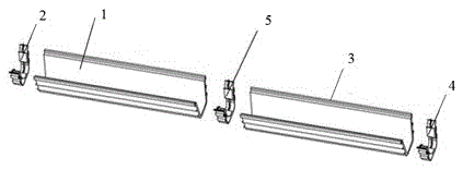
[0019] A drainage tank, comprising: a conductive core tank 1 for accommodating water flow, a positive fastener 2 and a negative fastener 4 placed at both ends of the drainage tank, a water-permeable insulating film 3 wrapping the conductive core tank 1, connecting the conductive core tanks 1 Connect fastener 5. The surface is covered with a water-permeable insulating film 3, which increases the safety performance during use and prevents the core groove from being blocked by impurities. There can be multiple conductive core grooves 1, which are connected by connecting fasteners 5; as a preferred method, the connecting fasteners 5 are plastic fasteners. During the electrolytic desaturation process, the water in the conductive core tank 1 is electrolyzed into hydrogen and oxygen. Therefore, after the air column formed in the drainage chann...


PUM

PropertyMeasurementUnit
Thicknessaaaaaaaaaa
Diameteraaaaaaaaaa

Abstract

The invention discloses a water draining groove. The water draining groove comprises conductive core grooves for containing water flow, a positive pole buckling part, a negative pole buckling part, water-pervious insulation films wrapping the conductive core grooves and a connecting buckling part connected between the conductive core grooves, wherein the positive pole buckling part and the negative pole buckling part are arranged at the two ends of the water draining groove. According to the plastic water draining groove, through an electrolytic saturated sand foundation, the good water draining effect can be ensured, the sandy soil saturation can be actively reduced, and the anti-liquefaction capability of the sand foundation can be improved.

Description

technical field [0001] A gutter, in particular a plastic gutter for electrolytic desaturation. Background technique [0002] The main function of the traditional drainage tank is to adjust the water source, which is widely used in various irrigation and drainage. However, there are some disadvantages: the construction period is long, and the surrounding sand and soil will be greatly damaged. At the same time, the construction steps are relatively cumbersome, and the construction cost is relatively high. At present, there are already plastic drainage channels in the project to replace the traditional drainage channels. By collecting and removing seepage water in the sand, the water pressure in the sand is reduced, and the soil and buildings can be prevented from soaking and deforming as much as possible. Destabilization occurs. However, these measures are only limited to problems such as seepage deformation, and have no significant effect on improving the anti-liquefaction ...

Claims


Application Information

Patent Timeline
IPC IPC(8): E02D3/10
CPCE02D3/10
Inventor 陈育民何森凯王翔鹰李文闻周晓智
Owner HOHAI UNIV
Why Eureka
Try Eureka