Profiled steel structure beam column joint for reverse construction of stiffened structure and construction method

A technology of beam-column joints and construction methods, which is applied in the direction of building structure, construction, and building material processing, can solve the problems of excessive cross-sectional size of beam-column joints, dense steel bars, and affecting building structures, etc., and achieve efficient construction methods. Save construction cost and promote the effect of value

Inactive Publication Date: 2016-06-08
SHANGHAI CONSTR NO 1 GRP +1
View PDF8 Cites 4 Cited by
  • Summary
  • Abstract
  • Description
  • Claims
  • Application Information

AI Technical Summary

Problems solved by technology

[0004] The object of the present invention is to provide a steel structure beam-column joint and its construction method with a rigid structure inversion method, which is used to solve the problem of setting a concrete ring beam or a column cap at the beam-column joint,

Method used


Image

  • Profiled steel structure beam column joint for reverse construction of stiffened structure and construction method
  • Profiled steel structure beam column joint for reverse construction of stiffened structure and construction method
  • Profiled steel structure beam column joint for reverse construction of stiffened structure and construction method

Examples


Example Embodiment

[0033] Example one

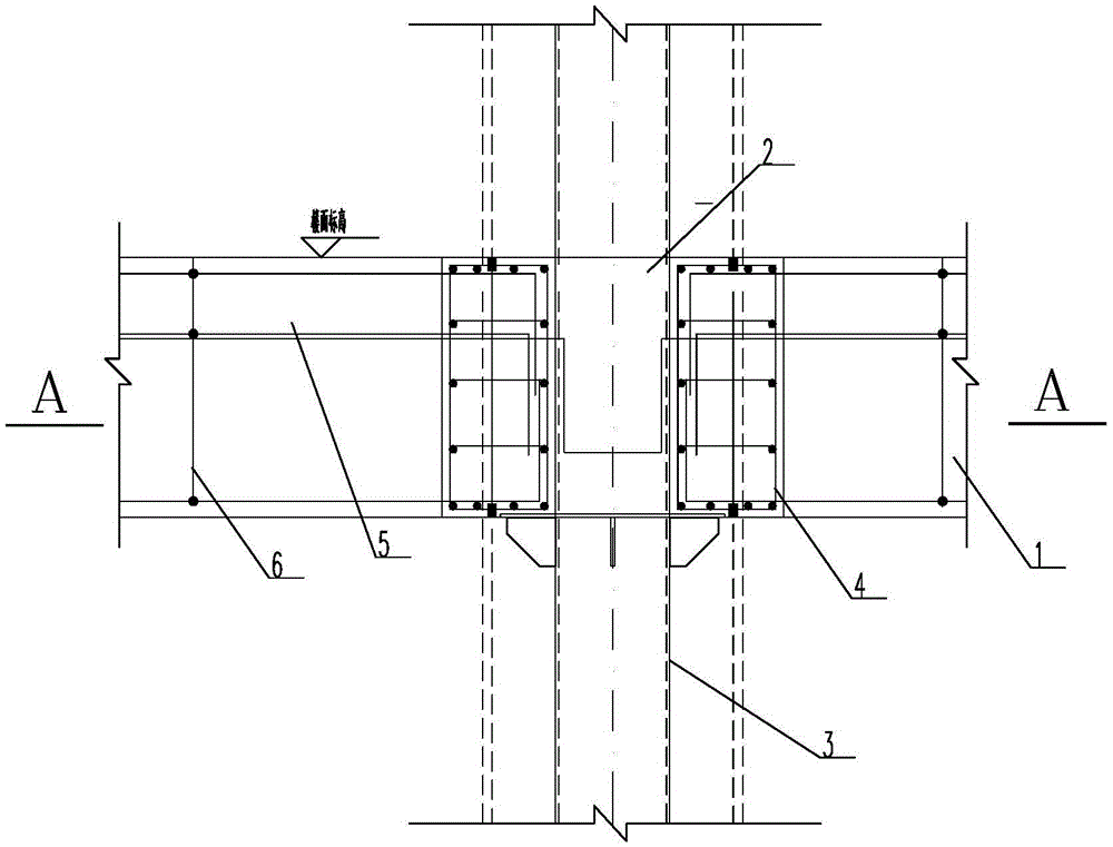
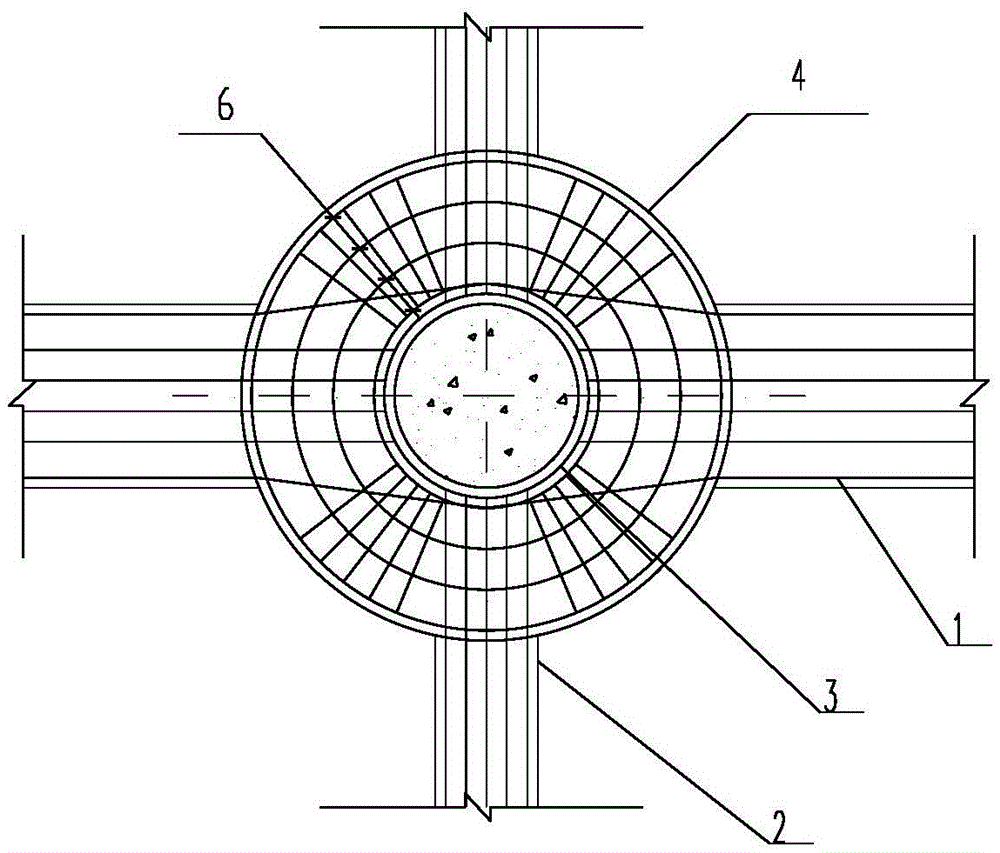
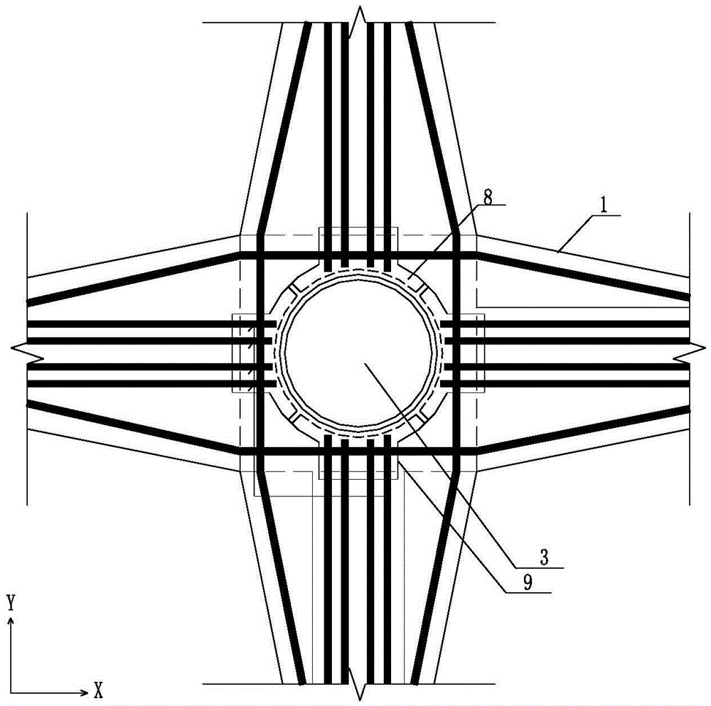
[0034] Such as Figure 3 to Figure 7 As shown, the stiff structure top-down steel structure beam-column connection. The stiff structure includes a frame beam 1 and a frame column 10 that are vertically intersected and fixed. The frame beam 1 is provided with an H-shaped steel beam (not shown) and a frame column 10 There is a round pipe column 3 inside. The H-shaped steel beam and round pipe column 3 are section steel structures. The outer wall of the round pipe column 3 at the beam-column node is welded with two transversely parallel steel ring plates 8, and the H-shaped steel near the beam-column node The end of the beam is sandwiched between two steel ring plates 8, and the steel ring plate 8 is also provided with a cantilever steel plate 9 along the length of the frame beam 1. The cantilever steel plate 9 has the same elevation and thickness as the steel ring plate 8 .

[0035] Specifically, a pair of transversely parallel steel ring plates 8 are welded to...

Example Embodiment

[0041] Example two

[0042] Correspondingly, this embodiment provides a construction method for a rigid structure top-down construction method for a beam-column joint of a steel structure. Please refer to Figure 3 to Figure 7 , A construction method of a rigid structure top-down construction method for a beam-column joint of a steel structure. The construction method includes the following steps:

[0043] S001: Making the steel ring plate 8 spare: Calculate the theoretical size of the steel ring plate 8 and establish a finite element calculation model of the steel ring plate 8 to determine the actual size of the steel ring plate 8. In this embodiment, the large-scale general finite element software ANSYS 12.1 is used, the round pipe string 3 and the steel ring plate 8 with the overhanging steel plate 9 both adopt the SEHLL93 unit, and the round pipe string 3 is consolidated at both ends. The steel is Q345B, the ideal elastoplastic constitutive model is adopted, and the yield str...


PUM

PropertyMeasurementUnit
Diameteraaaaaaaaaa

Abstract

The invention relates to a profiled steel structure beam column joint for reverse construction of a stiffened structure and a construction method and belongs to the technical field of building construction. By the adoption of the profiled steel structure beam column joint for reverse construction of the stiffened structure and the construction method, the problems that due to the fact that a concrete ring beam or a column cap is arranged on a traditional beam column joint, the sectional dimension of the beam column joint is too large, a building structure is affected, steel bars on the beam column joint are dense, and beam main steel bars of a frame beam cannot meet the requirement for the anchoring length are solved. According to the beam column joint, two parallel transverse steel ring plates are welded to the outer wall of a circular pipe column located on the beam column joint, the end of an H-shaped steel beam close to the beam column joint is arranged between the two steel ring plates in a clamped mode, and the steel ring plates are further provided with cantilever steel plates in the length direction of a frame beam. The construction method comprises the steps that firstly, the steel ring plates are manufactured for later use; secondly, the steel ring plates are welded to the circular pipe column on the beam column joint; thirdly, longitudinal column main steel bars of a frame column are made to penetrate through the gap between the cantilever steel plates which are adjacent in the axial direction; and finally, the beam main steel bars of the frame beam are arranged and bound.

Description

technical field [0001] The invention relates to the technical field of building construction, in particular to a steel structure beam-column joint and a construction method of a rigid structure reversed method. Background technique [0002] The rigid structure is composed of concrete, section steel, longitudinal steel bars and stirrups, and the basic components are frame beams and frame columns, such as column piles. The rigid structure has the advantages of high strength, small cross-sectional size of components, strong binding force with concrete, saving concrete, increasing usable space, reducing project cost, and improving project quality. Therefore, column piles are usually used in the construction of the top-down method of foundation pit. During the construction of beam-column joints of steel structure with conventional column pile reverse method, it is customary to set circular or square concrete column caps (hereinafter referred to as column caps) to realize the con...

Claims


Application Information

Patent Timeline
IPC IPC(8): E04B1/58E04G21/14
CPCE04B1/58E04G21/14
Inventor 朱毅敏彭韬吴中岳龚耀瑜王飞金伟袁峰
Owner SHANGHAI CONSTR NO 1 GRP
Why Eureka
Try Eureka