Valve external cooling system achieving cooling with seawater

A technology of cooling system and circulating water system, which is applied in the field of external cooling system using seawater cooling, can solve the problems of complex operation and maintenance, shortage of fresh water resources, low cooling efficiency, etc., and achieve simple system operation and management, saving fresh water resources, occupying small area effect

Inactive Publication Date: 2016-06-08
STATE GRID CORP OF CHINA +3
View PDF6 Cites 3 Cited by
  • Summary
  • Abstract
  • Description
  • Claims
  • Application Information

AI Technical Summary

Problems solved by technology

In addition, most DC converter stations often operate in isolated islands, and fresh water resources are even scarcer, which limits the promotion and construction of DC converter stations
[0003] The existing external cooling water system has the following problems: (1) The fresh water cooling system is conventionally used in the external cooling scheme of the valve, which has the disadvantages of large supply water and lower cooling efficiency compared with the seawater cooling system; (2) The fresh water cooling system Its external cooling system includes a large number of structures and equipment, such as closed cooling towers, spray pools, spray pumps, etc. If the fresh water source cannot guarantee two-way water supply, it must also be equipped with a large volume diverter valve that can supply water for three days The industrial water supply system, that is, the installation of industrial pools, industrial pump rooms and other ancillary structures, occupies a large area and is more complicated to operate and maintain
(3) For converter stations operating on isolated islands, the surrounding water supply pipe network is not sound or even missing, and fresh water sources are extremely precious. Using the traditional municipal pipe network diversion method requires additional investment in water supply pipe network construction, which will greatly improve the cooling system of the converter station. cost

Method used


Image

  • Valve external cooling system achieving cooling with seawater

Examples


Embodiment Construction

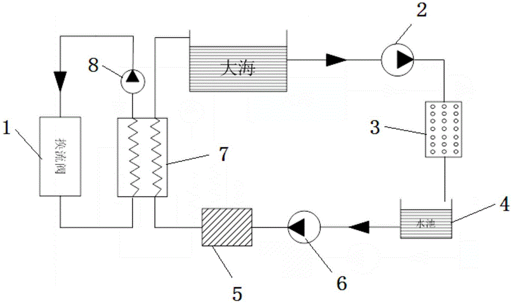
[0012] The present invention will be described in detail below in conjunction with the accompanying drawings and embodiments.

[0013] Such as figure 1 As shown, the present invention provides an external valve cooling system using seawater cooling, which includes a raw water intake system, a heat exchange system, a circulating water system and a diverter valve 1 . The raw water intake system leads seawater to the diverter valve 1 for storage as a heat exchange medium; the heat exchange system conducts heat exchange between the heat exchange medium in the diverter valve 1 and seawater to cool the heat exchange medium, and then provides the diverter valve 1 Cooling and heat exchange; the circulating water system circulates seawater to the diverter valve 1 and the heat exchange system.

[0014] Wherein, the raw water intake system includes a raw water pump 2 , a seawater delivery pipeline, a filter tank 3 and a pool 4 . One end of the seawater delivery pipeline is set in the s...


PUM


Abstract

The invention relates to a valve external cooling system achieving cooling with seawater. The system comprises a raw water obtaining system, a heat exchange system, a water circulation system and a converter valve. The raw water obtaining system guides the seawater into the converter valve to be stored as a heat exchange medium. The heat exchange system conducts heat exchange between the heat exchange medium in the converter valve and the seawater. The water circulation system conveys the seawater into the converter valve and the heat exchange system in a circulating mode. The raw material obtaining system comprises a raw water pump, a seawater conveying pipeline, a filtering pond and a pond. One end of the seawater conveying pipeline is arranged in the sea, the other end of the seawater conveying pipeline is connected with the inlet end of the filtering pond through the raw water pump, the outlet end of the filtering pond is connected with an inlet of the pond through the seawater conveying pipeline, and filtered seawater is stored in the pond. The valve external cooling system can effectively save fresh water resources and is good in cooling effect.

Description

technical field [0001] The invention relates to an external valve cooling system, in particular to an external valve cooling system using seawater cooling applied in the field of high-voltage direct current transmission. Background technique [0002] At present, in the high-voltage direct current transmission system, the external cooling water system is an important component of the heat dissipation system of the converter valve, and its operation directly affects the power transmission capacity of the entire direct current system. Therefore, it is particularly important to ensure the stable, reliable and efficient operation of the external cooling water system. Today, when fresh water resources are scarce, seawater instead of fresh water as industrial cooling water is one of the important ways to solve the fresh water resource crisis in coastal cities and regions in our country. In addition, most DC converter stations often operate in isolated islands, and fresh water reso...

Claims


Application Information

Patent Timeline
Patent Type & Authority Applications(China)
IPC IPC(8): F16K49/00
CPCF16K49/005
Inventor 王赞常浩马为民石岩陈琳乐波梅念陈东吴方劼吴延坤傅晓凌
Owner STATE GRID CORP OF CHINA
Why Eureka
Try Eureka