Detection device, method and system of approach switch
A technology of a proximity switch and a detection method, applied in the field of devices and systems, and detection methods of proximity switches, can solve the problems of low detection efficiency of proximity switches and the like, and achieve the effect of improving detection efficiency
- Summary
- Abstract
- Description
- Claims
- Application Information
AI Technical Summary
Problems solved by technology
Method used
Image
Examples
Embodiment 1
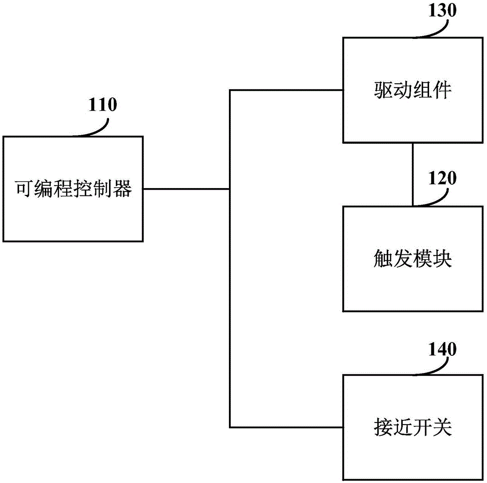
[0031] figure 1 It is a logic block diagram of a detection system of a proximity switch according to Embodiment 1 of the present invention. The detection system includes a programmable controller 110, a trigger module 120 and a drive assembly 130, wherein: the programmable controller 110 triggers the drive assembly 130 to drive the trigger module 120 to move; the trigger module 120 triggers at least two Proximity switch 140: the programmable controller 110 determines whether the at least two proximity switches 140 are normal according to whether the proximity switch 140 at the corresponding position is triggered when the trigger module 120 moves.
[0032] Among them, the programmable controller 110 (ie, PLC, ProgrammableLogicController) is used to perform operations such as stored logic operations and sequence control, timing, counting, and arithmetic operations, and through digital or analog input interfaces and output interfaces, control The control unit for the correspondi...
Embodiment 2
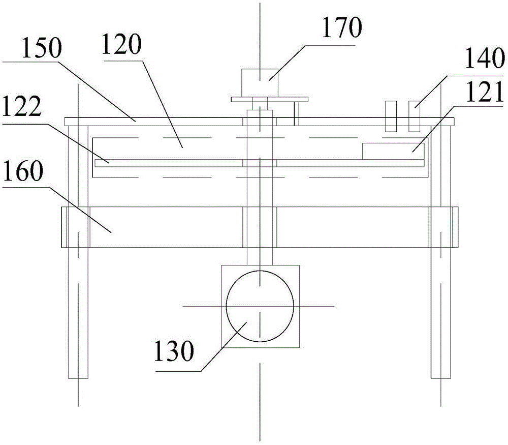
[0036] figure 2 It is an assembly drawing of the tooling structure of the detection system of the proximity switch according to the second embodiment of the present invention. The detection system includes figure 1 All the functional units of the detection system of the proximity switch are shown, and on the basis of them, they are improved, and the improvements are as follows:
[0037] In order to realize the batch detection of contact switches, the tooling for the batch testing can be designed, and the structure of the designed tooling can be adjusted according to the actual situation. like figure 2 As shown, the trigger module 120 may include a first slider 121 and a rotating platform 122 , the first slider 121 is fixedly mounted on the rotating platform 122 and rotates with the rotating platform 122 .
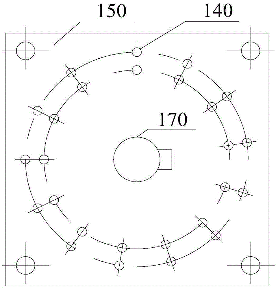
[0038] like figure 2 As shown, the detection system of the proximity switch includes a sensing platform 150, a base 160, a drive assembly 130, a trigger module 120, ...
Embodiment 3
[0050] Image 6 It is a flow chart of the detection method of the proximity switch according to the third embodiment of the present invention. by including as Figure 7 The detection device shown carries out the detection method.
[0051] refer to Image 6 , in step S610, acquire the mobile location information of the trigger module.
[0052] Specifically, based on figure 2 The detection system of the proximity switch, when it is necessary to detect multiple proximity switches, the multiple proximity switches can be installed on the sensing platform. In order to improve the detection efficiency, multiple proximity switches can be installed in the radial direction of the rotating platform, which can be The programming controller can send the speed signal to the motor driver, and the motor driver can convert the speed signal into a pulse signal and send it to the stepping motor, and the stepping motor drives the rotating platform to rotate. The programmable controller can ...
PUM
 Abstract
Description
Claims
Application Information
 - R&D
- Intellectual Property
- Life Sciences
- Materials
- Tech Scout
- Unparalleled Data Quality
- Higher Quality Content
- 60% Fewer Hallucinations
Browse by: Latest US Patents, China's latest patents, Technical Efficacy Thesaurus, Application Domain, Technology Topic, Popular Technical Reports.
© 2025 PatSnap. All rights reserved.Legal|Privacy policy|Modern Slavery Act Transparency Statement|Sitemap|About US| Contact US: help@patsnap.com


